Panel/wall mounting – Rockwell Automation 1440-VDRP06-00RH XM-160/161/162 Direct Vibration Module User Manual
Page 24
Publication GMSI10-UM025C-EN-P - August 2010
16 Installing the XM-160/161/162 Direct Vibration Module
Panel/Wall Mounting
Installation on a wall or panel consists of:
• laying out the drilling points on the wall or panel
• drilling the pilot holes for the mounting screws
• installing the terminal base units and securing them to the wall or panel
Use the following steps to install the terminal base on a wall or panel.
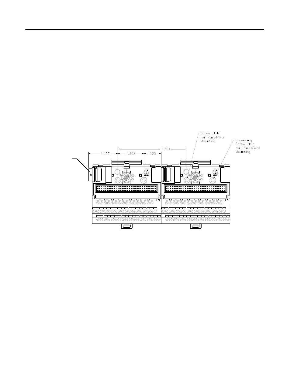
1. Lay out the required points on the wall/panel as shown in the drilling
dimension drawing below.
2. Drill the necessary holes for the #6 self-tapping mounting screws.
3. Secure the terminal base unit using two #6 self-tapping screws.
4. To install another terminal base unit, retract the side connector into the
base unit. Make sure it is fully retracted.
5. Position the terminal base unit up tight against the neighboring terminal
base. Make sure the hook on the terminal base slides under the edge of
the terminal base unit.
6. Gently push the side connector into the side of the neighboring terminal
base to complete the backplane connection.
7. Secure the terminal base to the wall with two #6 self-tapping screws.
Side Connector