Connecting the transducers – Rockwell Automation 1440-VDRP06-00RH XM-160/161/162 Direct Vibration Module User Manual
Page 34
Publication GMSI10-UM025C-EN-P - August 2010
26 Installing the XM-160/161/162 Direct Vibration Module
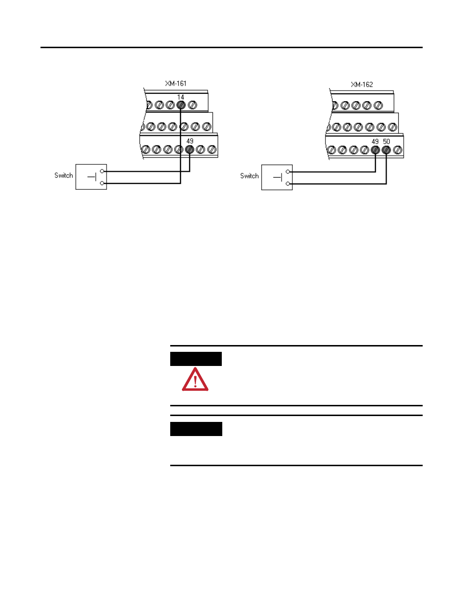
Figure 2.13 Setpoint Multiplication Connections
Connecting the Transducers
The Direct Vibration Modules can accept input from any Allen-Bradley
non-contact eddy current probe, a standard IEPE accelerometer, a velocity
transducer, or AC voltage output measurement device.
Connecting an IEPE Accelerometer
The following figures show the wiring of an IEPE accelerometer to the
terminal base unit.
ATTENTION
You may ground the cable shield at either end of the cable.
Do not ground the shield at both ends. Recommended
practice is to ground the cable shield at the terminal base
and not at the transducer. Any convenient Chassis terminal
may be used (see Terminal Block Assignments on page 17).
IMPORTANT
The internal transducer power supply is providing power to
the IEPE accelerometer. Make certain the IEPE Power
parameter is enabled. Refer to IEPE Buffer Power and
Signal Detection Parameters on page 58.