Connecting a powered sensor – Rockwell Automation 1440-VDRP06-00RH XM-160/161/162 Direct Vibration Module User Manual
Page 51
Publication GMSI10-UM025C-EN-P - August 2010
Installing the XM-160/161/162 Direct Vibration Module 43
Connecting a Powered Sensor
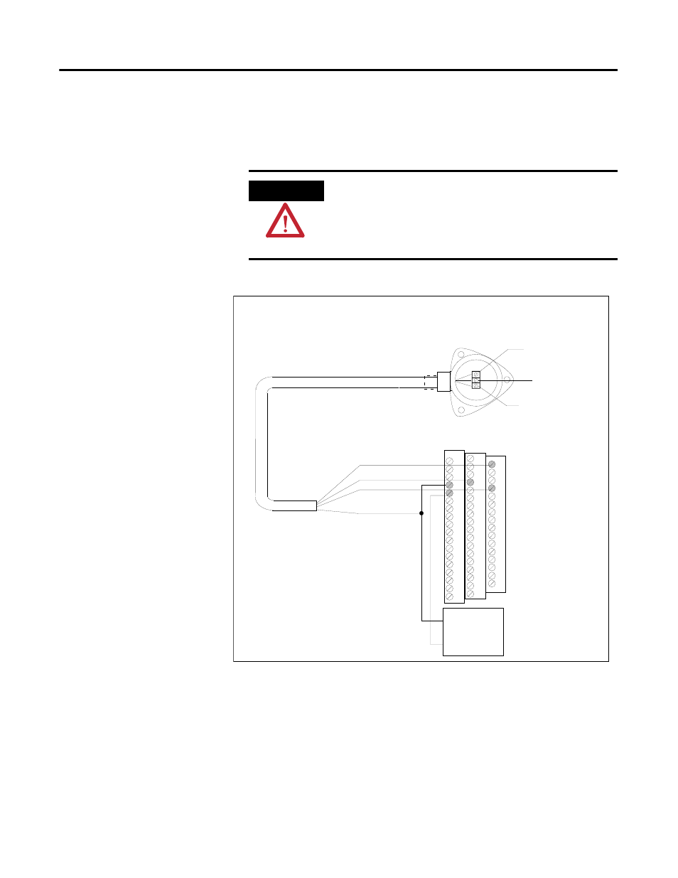
The figures below show the wiring of a powered sensor, such as the Model 580
Vibration Pickup, to the terminal base unit.
Figure 2.38 Powered Sensor to Channel 1 Wiring
ATTENTION
You may ground the cable shield at either end of the cable.
Do not ground the shield at both ends. Recommended
practice is to ground the cable shield at the terminal base
and not at the transducer. Any convenient Chassis terminal
may be used (see Terminal Block Assignments on page 17).
0
37
+24V DC
Common
Signal
3
19
Channel 1 Input Signal
Signal Common
Shield
+24V DC
TYPICAL WIRING FOR MODEL 580 VIBRATION PICKUP
TO XM-160/161/162 DIRECT VIBRATION MODULE CHANNEL 1
Cable shield not
connected at this end
+
-
+24V DC
Power
Supply
38