Rockwell Automation 1771-QC , D17716.5.25 SER/B SERVO POS User Manual
Page 74
Installing the Assembly
Chapter 6
6Ć24
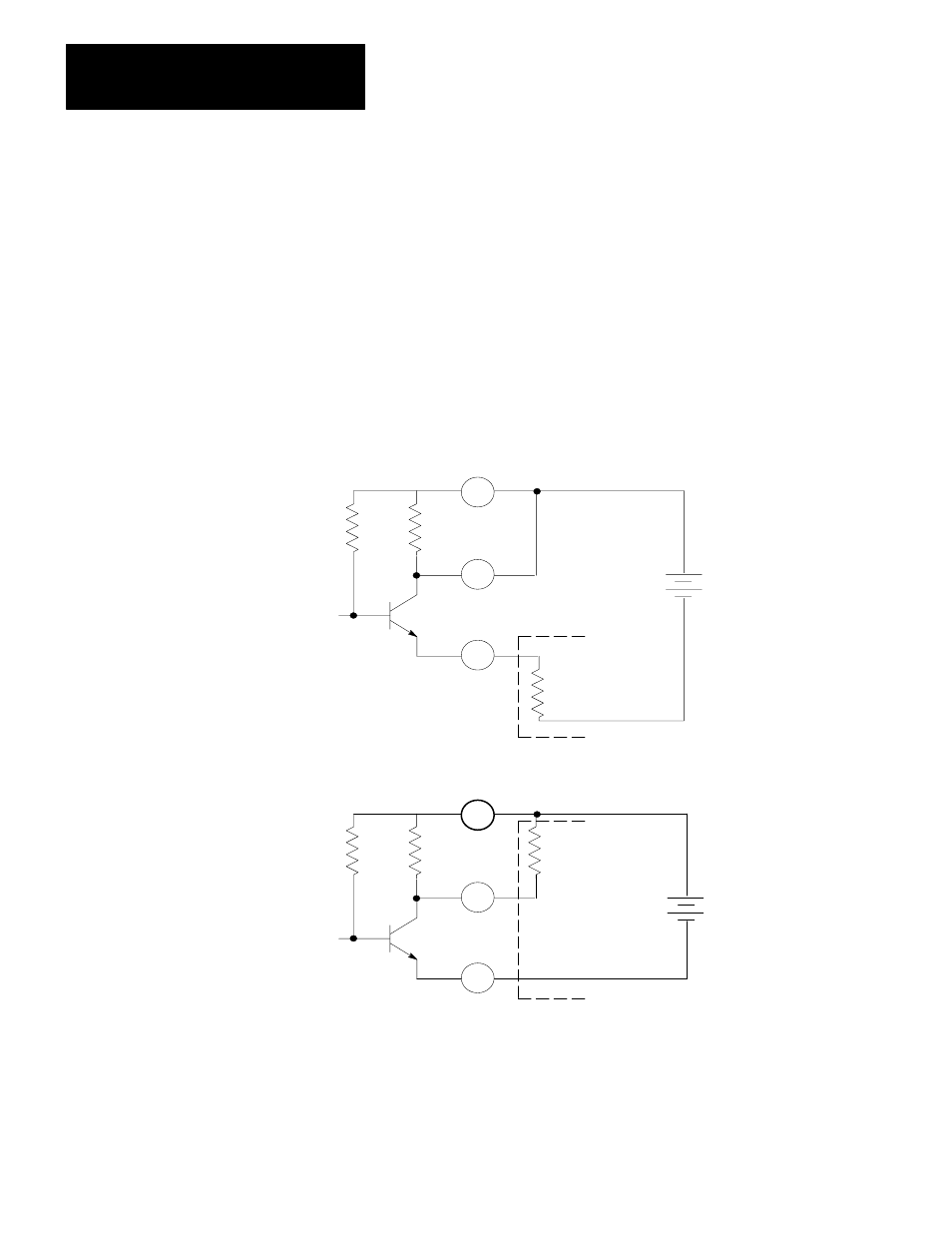
Connecting Drive Disable
Figure 6.13 shows details of how to connect drive disable for two basic
types of configurations. Some servo drives require a current source
connected to an input to enable the drive. Some require a current sink
connected to an input to enable the drive. We provide all three connection
points (base, emitter, and collector) of the drive disable circuit to provide
you with a flexibility of connecting it in a configuration that applies to
your servo drive.
Figure 6.13
Connection Details for Two Basic Drive Configurations
Q1
8.2k
+
-
Customer's Drive
Disable Power Supply
(5 to 30V dc)
Drive Disable
Input on Customer's
Servo Drive
8
9
10
a) Current Sourcing Configuration
Drive Enable Q1 on: Current is sourced
from terminal 10 into the servo drive.
Drive Disabled Q1 off: Current into the
servo drive is inhibited.
Q1
8.2k
+
-
8
9
10
Customer's Drive
Disable Power Supply
(5 to 30Vdc)
Drive Disable
Input on Customer's
Servo Drive
b) Current Sinking Configuration
Drive Enable Q1 on: Current is sunk thru
terminal 9 and Q1.
Drive Disabled Q1 off: Current thru Q1 is
inhibited. Terminal 9 is pulled up to the
potential of terminal 8.
12023
For the drive disable circuit, you must provide a 5-30V dc power supply
which can provide 100mA maximum. The power supply can be separate
or an integral part of the servo drive. Each of the configurations of figure
6.13 includes a separate power supply.