Parameter block appendix c – Rockwell Automation 1771-QC , D17716.5.25 SER/B SERVO POS User Manual
Page 237
Parameter Block
Appendix C
CĆ6
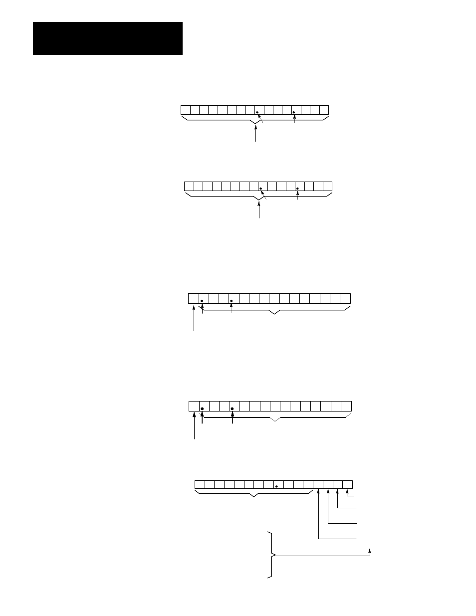
17 16 15 14 13 12 11 10 07 06 05 04 03 02 01 00
-Software Travel Limit
Word 22 (Axis 1)
Word 41 (Axis 2)
Word 60 (Axis 3)
17 16 15 14 13 12 11 10 07 06 05 04 03 02 01 00
+ Software Travel Limit
Word 21 (Axis 1)
Word 40 (Axis 2)
Word 59 (Axis 3)
inch
metric
decimal
point
decimal
point
inch
metric
decimal
point
decimal
point
Negative software travel limit. An
axis position value in inches or
meters, BCD format.
Positive software travel limit. An
axis position value in inches or
meters, BCD format.
CAUTION: If programmed values are zero, there are
no software travel limits. To guard against damage to
equipment, exercise caution when operating an axis
without software travel limits.
17 16 15 14 13 12 11 10 07 06 05 04 03 02 01 00
Backlash Takeup Distance
Word 23 (Axis 1)
Word 42 (Axis 2)
Word 61 (Axis 3)
inch
metric
Sign:
0 = +
1 = -
decimal
point
decimal
point
Distance axis overshoots when initial
approach to endpoint is from
direction opposite that specified in bit
17.
Axis approaches all
endpoints moving in
the direction specified
by the sign (bit 17).
17 16 15 14 13 12 11 10 07 06 05 04 03 02 01 00
Offset
Word 24 (Axis 1)
Word 43 (Axis 2)
Word 62 (Axis 3)
inch
metric
Sign:
0 = +
1 = -
decimal
point
decimal
point
Offset value, inches or
millimeters, BCD format
17 16 15 14 13 12 11 10 07 06 05 04 03 02 01 00
FE Reduction, Tach Conversion Factor
Word 25 (Axis 1)
Word 44 (Axis 2)
Word 63 (Axis 3)
BCD following error reduction value (0-99.9%)
0 = 0
1 = 0.0625
0 = 0
1 = 0.125
0 = 0
1 = 0.250
0 = 0
1 = 0.500
11050
Total value is the sum of the
selected values.
Used if full scale analog output voltage is greater
than tachometer voltage for a given rpm. Refer to
the tachometer calibration procedure in chapter 9.