Rockwell Automation 1771-QC , D17716.5.25 SER/B SERVO POS User Manual
Page 109
Formatting and Interpreting Data Blocks
Chapter 7
7Ć27
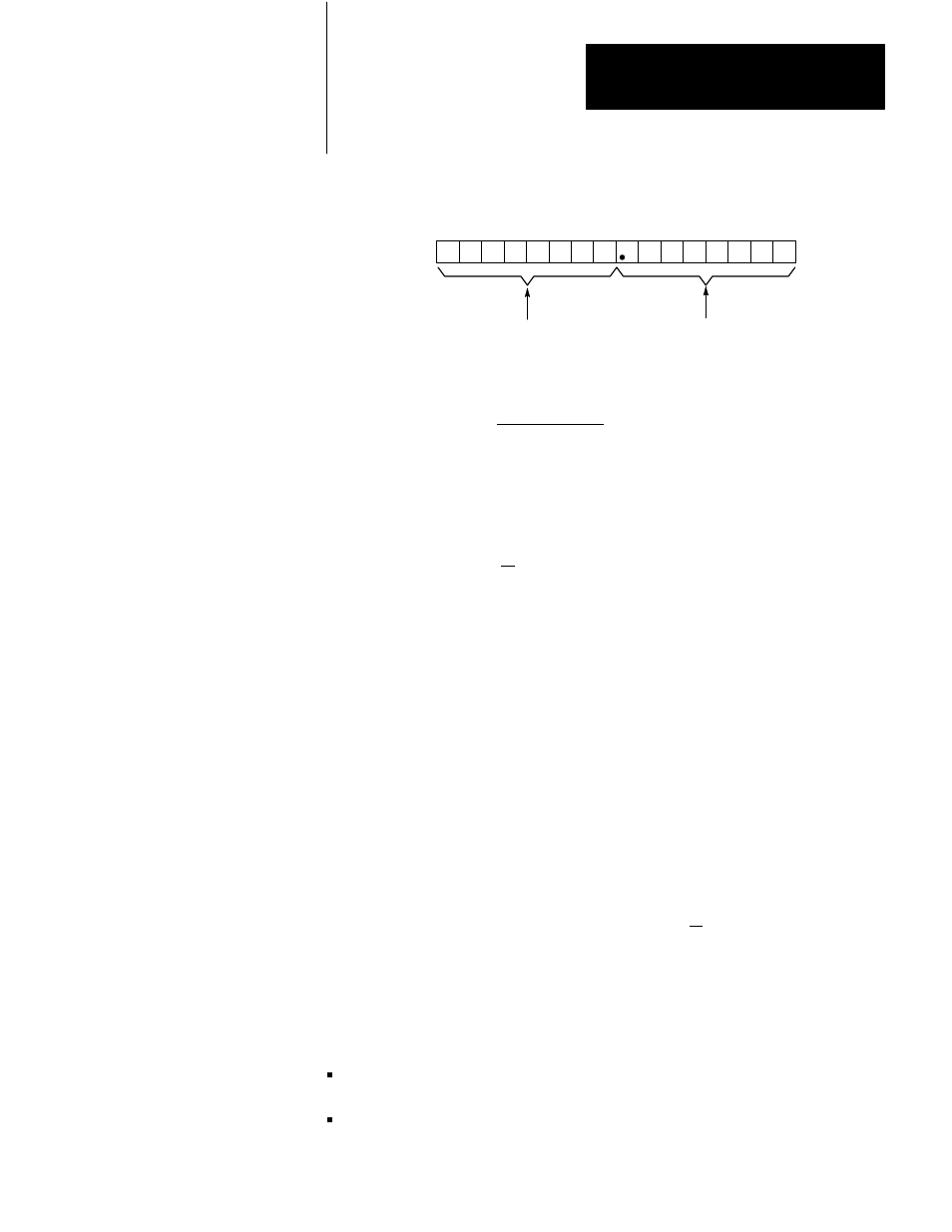
Figure 7.17
InĆposition Band, Gain Reduction Factor Word
17 16 15 14 13 12 11 10 07 06 05 04 03 02 01 00
Word 11 (Axis 1)
Word 30 (Axis 2)
Word 49 (Axis 3)
This BCD value (99 max) times 2 is
the inĆposition band in increments of
feedback resolution.
11039
Gain reduction factor
Gain Reduction Factor =
Reduced Gain
Initial Gain
For example, if the initial gain is one, and you want the reduced gain to be
0.5, program .50 as the value for gain reduction factor.
Gain Reduction Factor =
.5
= .50
1
The gain reduction factor must be less than 1.0. If you program zero, the
system gain for any axis speed will be the initial gain. If gain break
velocity is zero and you program a non-zero gain reduction factor, system
gain for any axis speed is the initial gain times the gain reduction factor.
Enter the gain reduction factor in BCD format.
InĆPosition Band
The size of the in-position band is measured in increments of the feedback
resolution of the axis. Program a 2-digit BCD value that is half the
desired in-position band in bits 10-17 of the in-position-band and
gain-break-factor word (Figure 7.17). If you program zero as the
in-position band parameter value, the servo positioning assembly
automatically makes the active in-position band +2 feedback increments.
The 1771-M3 controller turns on the in-position bit when the done bit is
on in the status block and the axis is within the in-position band.
The axis must be in-position before the following actions can take place:
Manual mode commands are not executed unless the in-position bit is
on.
In auto mode, the start command is not executed unless the in-position
bit in the status block is on.