Rockwell Automation 1771-QC , D17716.5.25 SER/B SERVO POS User Manual
Page 121
Formatting and Interpreting Data Blocks
Chapter 7
7Ć39
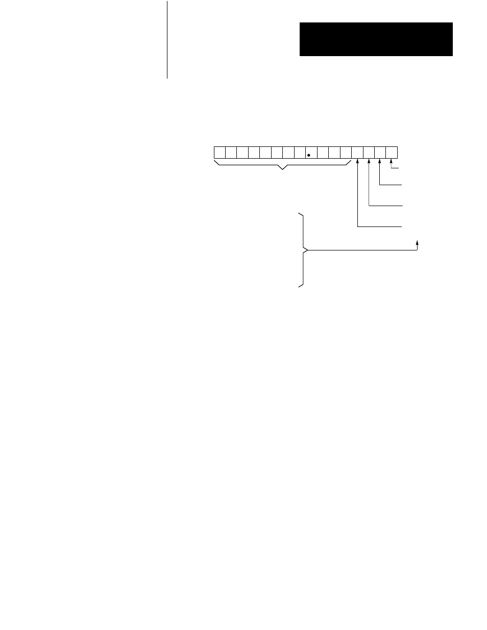
Figure 7.28
Following Error Reduction/Tachometer Conversion Factor Word
17 16 15 14 13 12 11 10 07 06 05 04 03 02 01 00
FE Reduction, Tach Conversion Factor
Word 25 (Axis 1)
Word 44 (Axis 2)
Word 63 (Axis 3)
11050
BCD following error reduction value (0-99.9%)
0 = 0
1 = 0.0625
0 = 0
1 = 0.125
0 = 0
1 = 0.250
0 = 0
1 = 0.500
Total value is the sum of the
selected values.
Used if full scale analog output
voltage is greater than tachometer
voltage for a given rpm. Refer to
the tachometer calibration
procedure in chapter 9.
Each of bits 0 thru 3 corresponds to a factor. The total factor used by
loss-of-feedback detection equals the sum of the individual factors
selected.
If you are not using the loss-of-feedback detection feature, or if
tachometer voltage is greater than or equal to 10V, program zero for all
bits of this word.
Following Error Reduction
The servo positioning assembly accepts the BCD value you enter into bits
04 thru 17 as the following error reduction value (Figure 7.28).
You can command a reduction of the following error by 0 through 99.9%.
The 1771-ES expander reduces the following error through feed
forwarding without increasing the positioning loop gain.
Consider an example in which you have entered an initial gain value of
1.00. With an axis speed of 10 ipm, without following error reduction, the
following error would be 10 mils.