Rockwell Automation 1771-QC , D17716.5.25 SER/B SERVO POS User Manual
Page 105
Formatting and Interpreting Data Blocks
Chapter 7
7Ć23
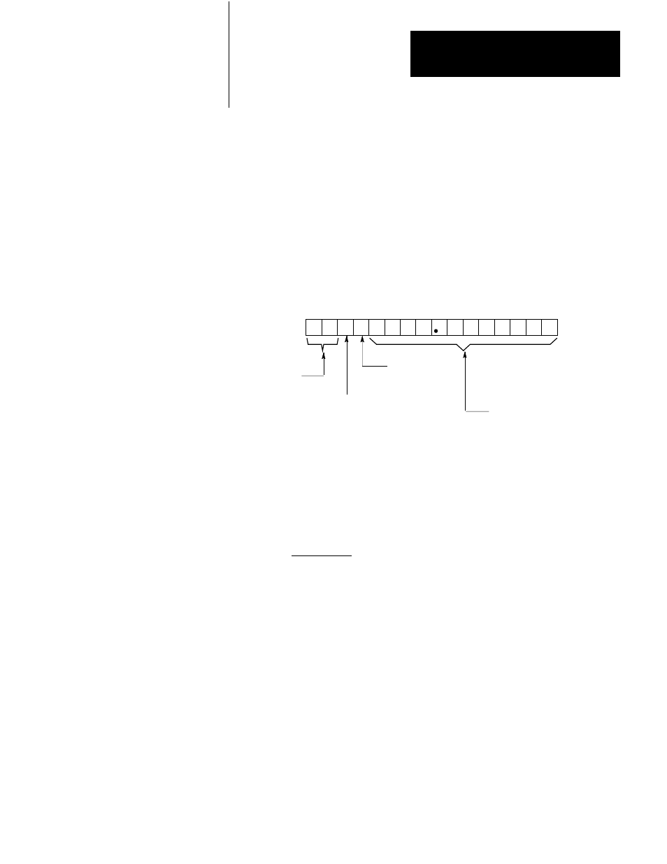
InitialĆGain/Multipliers
Bits 0 thru 13 of this word (Figure 7.13) specify the servo gain for this
axis at speeds below the gain break speed specified in word 10. You must
enter gain values in BCD format, from 0.01 to 9.99 ipm/mil or from 0.01
to 9.99 mmpm/mil. (A mil is 0.001 inch or 0.001 mm.)
Figure 7.13
Feedrate Multiplier, Encoder Lines Multiplier, and Initial Gain Word
17 16 15 14 13 12 11 10 07 06 05 04 03 02 01 00
Feedback Multiplier, Encoder Lines Multiplier, Loss-of-marker, Initial Gain
Word 9 (Axis 1)
Word 28 (Axis 2)
Word 47 (Axis 3)
Initial Gain, ipm/mil or
mmpm/mil, BCD format.
(1 mil = 0.001 inch or 0.001
millimeter.)
Feedback
Multiplier
01 = x 1
10 = x 2
00 = x 4
Encoder
Lines
Multiplier
0 = x 1
1 = x 4
(See preceding
word.)
Loss-of-marker
detection
0 = disabled
1 = enabled
11035
Servo gain is the ratio of axis speed to following error:
Gain = Axis Speed
Following Error
Following error is the difference between the axis position commanded by
the servo expander and the actual axis position indicated by encoder
feedback.
Servo gain affects axis response to positioning commands from the
1771-ES expander module. Figure 7.14 shows how different gain values
affect system responsiveness. The horizontal axis represents following
error. The vertical axis represents analog output voltage. Since analog
output voltage is directly proportional to axis speed, you can use the
vertical axis to represent either variable.
If gain is relatively high, following error will be relatively small, because
the system will be more sensitive to changes in following error. If gain is