Plc 3 block transfer timing, 8ć14 – Rockwell Automation 1771-QC , D17716.5.25 SER/B SERVO POS User Manual
Page 175
Chapter 8
8Ć14
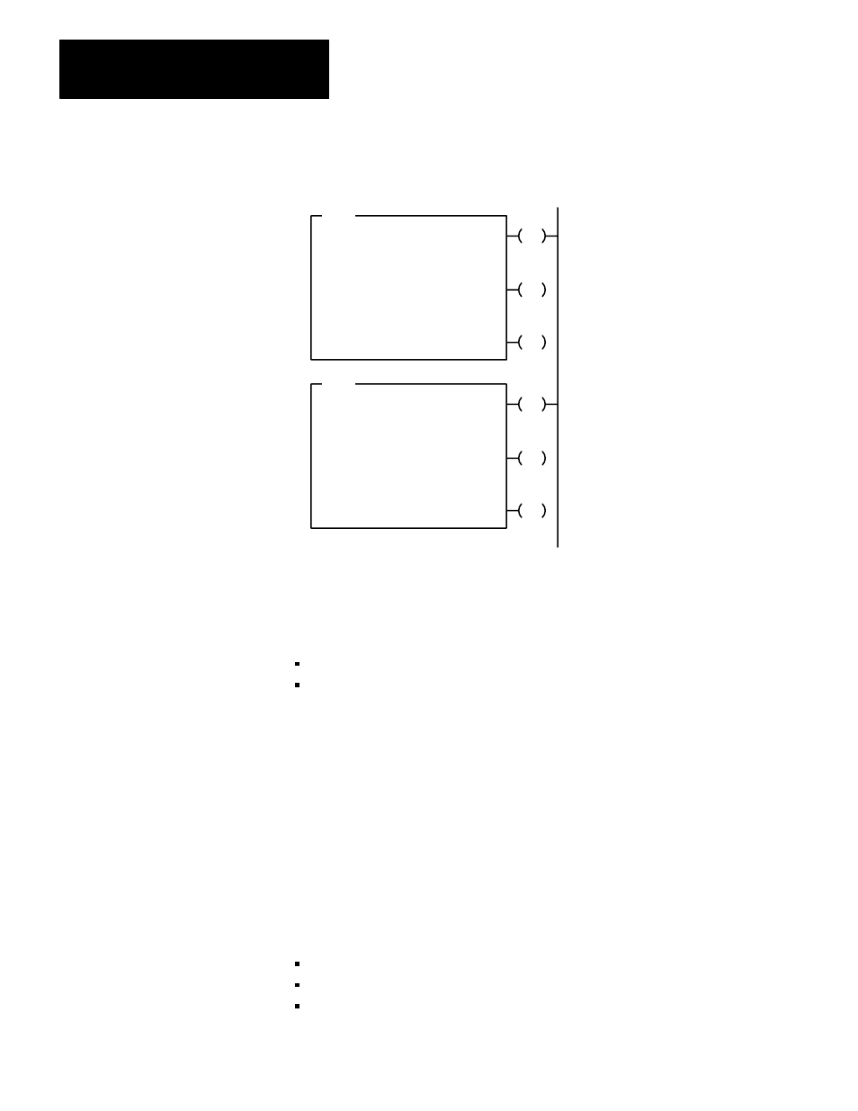
Figure 8.5
BlockĆtransfer Instructions for PLCĆ3 Controllers
EN
BTR
BLOCK XFER READ
RACK:
GROUP:
MODULE:
DATA:
001
1
1 = HIGH
FI001:0005
DN
LENGTH:
0
CNTL:
FB001:0000
ER
CNTL
12
CNTL
15
CNTL
13
EN
BLOCK XFER WRITE
RACK:
GROUP:
MODULE:
DATA:
001
1
1 = HIGH
FO001:0004
DN
LENGTH:
0
CNTL:
FB001:0000
ER
CNTL
02
CNTL
05
CNTL
03
Block transfer instructions use two files when transferring data and
commands between the block transfer module and the PLC-3 processor:
a data file that contains data being transferred
a control file that contains control bits, module location, data table
address and length of the data file
The I/O scanner directs communication between the block-transfer
module and processor. Once the block-transfer instruction is enabled, the
scanner directs the transfer of data to or from the enabled block transfer
module according to the information contained in the instruction’s control
file. Once the instruction is enabled, the PLC-3 processor automatically
sets and resets the control bits in accordance with the various steps
required to execute the read or write operation.
The execution time required to complete a read/write block transfer
depends on factors that include the number of:
words of user program
active I/O channels on the scanner
I/O chassis entries on the I/O chassis scanning sequence list for the
channel
PLCĆ3 Block Transfer Timing