Connecting to terminals, 6ć10, Installing the assembly chapter 6 – Rockwell Automation 1771-QC , D17716.5.25 SER/B SERVO POS User Manual
Page 60
Installing the Assembly
Chapter 6
6Ć10
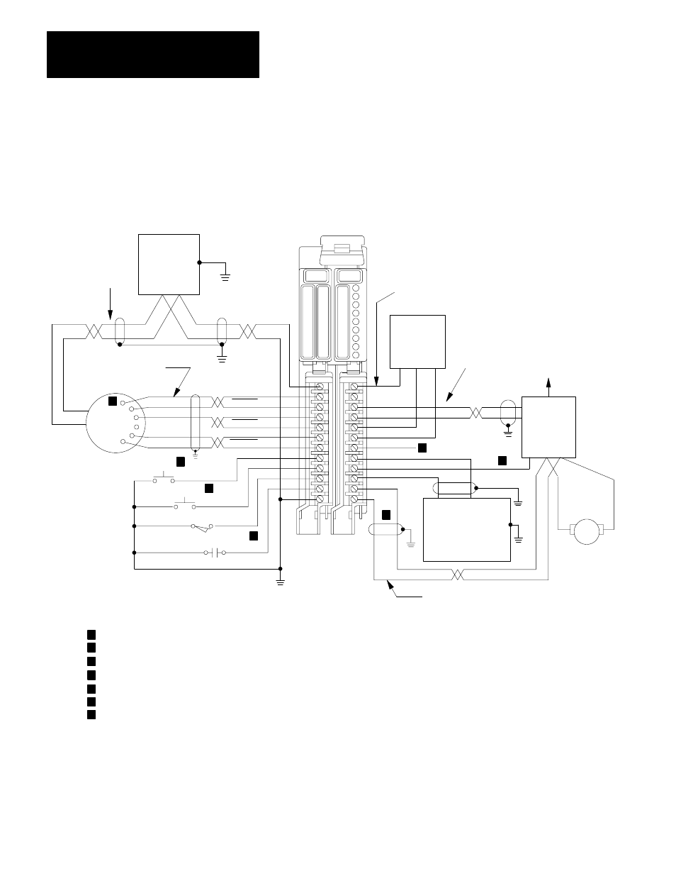
Make connections to the 1771-ES expander as shown in Figure 6.7.
Figure 6.7
Simplified I/O Terminal Connection Diagram
15V dc
For DAC
(Customer
Supplied)
+ Comm -
+-
Unused
Belden #8761 or
equivalent
(50ft. max.)
Servo
Drive
(Customer
Supplied)
To Servo
Motor
+
-
10V
Command
Return
5 to 30V dc Drive
Disable Supply
(Customer
Supplied)
-
+
Drive Disable
High
Low
Tach
Belden 8761 or
equivalent (50ft. max.)
NOTES:
If equipment permits, one supply can be used for encoder and input circuits. Current requirements depend on hardware configuration.
In the auto mode, the module accepts this input as the hardware start signal (figure 6.9).
In the auto mode, the module accepts this input as the feedrate enable signal (figure 6.9).
The module generates a hardware done signal at this +15V dc driver output terminal (figure 6.12).
Refer to figures 6.10 and 6.11.
Refer to figure 6.8.
Refer to figures 6.13 and 6.14.
Refer to figure 6.15.
Belden #8725 or
equivalent
(50ft. max.)
CH. A
CH. A
CH. B
CH. B
Marker
Marker
TTL
Output
Encoder
2
Hardware STO P
HOME LS
JOG REV
JOG FWD
+
-
12017
5 to 30V DC
Input Power
Supply
(customer
supplied)
Belden 8761 or
equivalent
(50 ft max)
1
+-
Belden 8723 or
equivalent (50ft max)
5
4
3
6
7
1
2
3
4
5
6
7
Connecting to Terminals