4 - positioning with allen-bradley pc, Chapter objectives, Where the servo positioning assembly fits in – Rockwell Automation 1771-QC , D17716.5.25 SER/B SERVO POS User Manual
Page 25
Chapter
4
4Ć1
Positioning With an AllenĆBradley Programmable
Controller
The previous chapter described concepts of closed-loop positioning. This
chapter describes where the servo positioning assembly fits into a
positioning system, and how the servo positioning assembly
communicates with the PC processor.
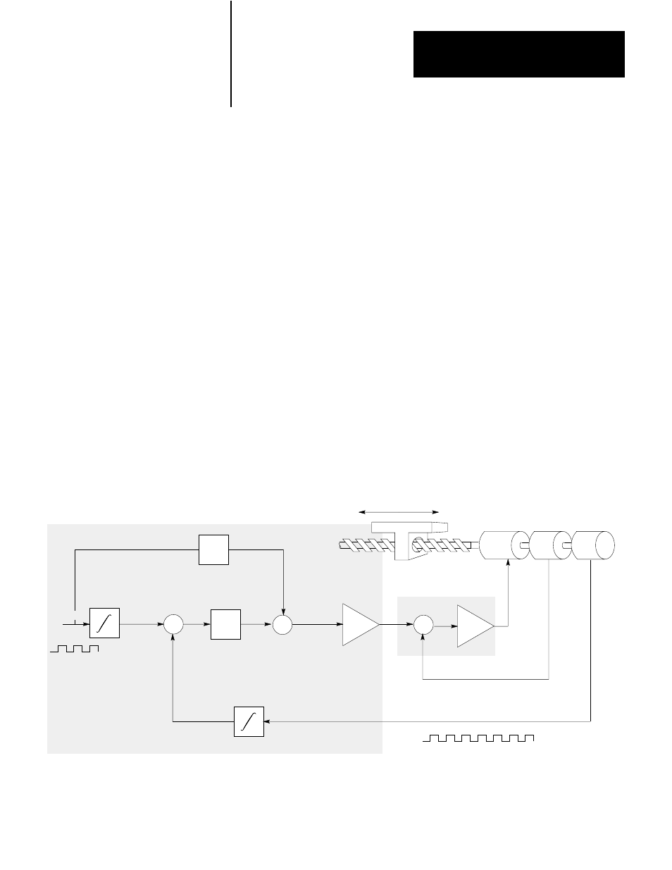
Figure 4.1 shows where the servo positioning assembly and a servo drive
fit in the positioning system we described in the previous chapter. The
servo drive contains the velocity loop summing point and amplifier. The
servo positioning assembly contains the positioning loop summing point
and the feed forward summing point. The servo positioning assembly
sends the analog velocity command signal to the servo drive.
Figure 4.1
Where the Servo Positioning Assembly Fits in a Positioning System
Axis Motion
Motor
Tach
-
+
Velocity
Command
Velocity Feedback
Encoder
Incremental Position Feedback
K1
-
+
Axis
Feedrate
Position
Command
Following
Error
D/A
K2
+
+
12005
Servo Drive
Servo Positioning Assembly
Position
Feed
Forward
Figure 4.2 shows where the servo positioning assembly fits in a PC
system. The PC processor constantly communicates with the servo
Chapter Objectives
Where the Servo Positioning
Assembly Fits In