Chapter 8 – Rockwell Automation 1771-QC , D17716.5.25 SER/B SERVO POS User Manual
Page 165
Chapter 8
8Ć4
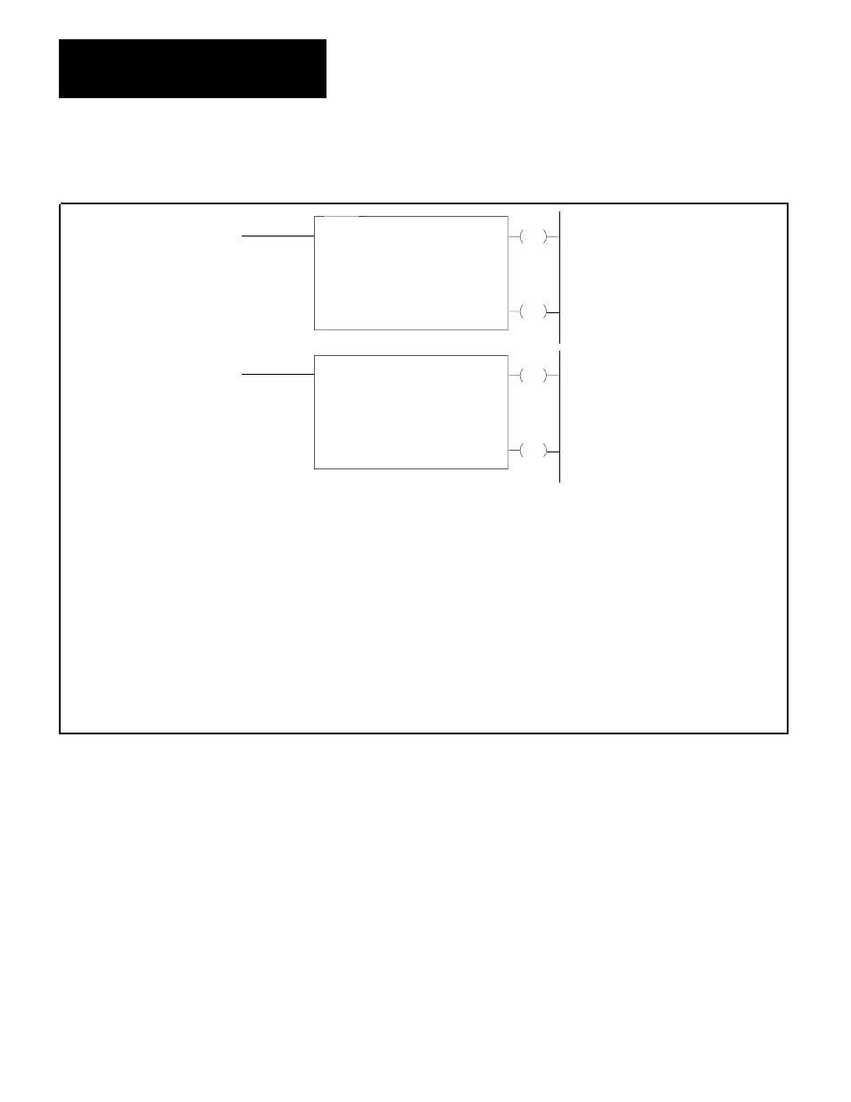
Figure 8.2
Block Transfer Instructions for PĆ2/30 and Mini PLCĆ2/15
EN
BLOCK XFER READ
DATA ADDR
MODULE ADDR
BLOCK LENGTH
FILE
030
100
01
110 - 110
DN
010
07
110
07
EN
BLOCK XFER WRITE
DATA ADDR
MODULE ADDR
BLOCK LENGTH
FILE
030
100
01
110 - 110
DN
010
06
110
06
Data Address
8
above the data address.)
Module Address
Block Length
File
Enable Bit (EN)
Don Bit (DN)
: First possible address in accumulated vaue area of data table.
: RGS Ć R = rack, G = module group, S = Slot number. (This value is stored in the data address word.)
: Number of words to be transferred. (00 can be entered for default value or for 64 words.)
: Address of first word in the file. (This value is stored in the 100
: In the output image table word for the module. Set on when rung containing the instruction is true.
: In the input image table word for the module. Remains on for 1 scan following successful transfer.
Figure 8.3 shows an example of data table arrangement for a read block
transfer.
Data table words assigned for block storage must not include reserved
processor work areas. That is, you must ensure that you assign starting
addresses for the block so that the words requested by the 1771-M3
controller do not include words in the processor work area. If the PC
attempts to transfer processor work area words to the 1771-M3 controller,
the PC can lock up, out of communication with the 1771-M3 controller.
For PLC-2-family processors, store blocks at data table addresses above
200
8
, and no block should begin less than 64 words from the start of the
user program.