Rockwell Automation 1771-QC , D17716.5.25 SER/B SERVO POS User Manual
Page 21
Positioning Concepts
Chapter 3
3Ć8
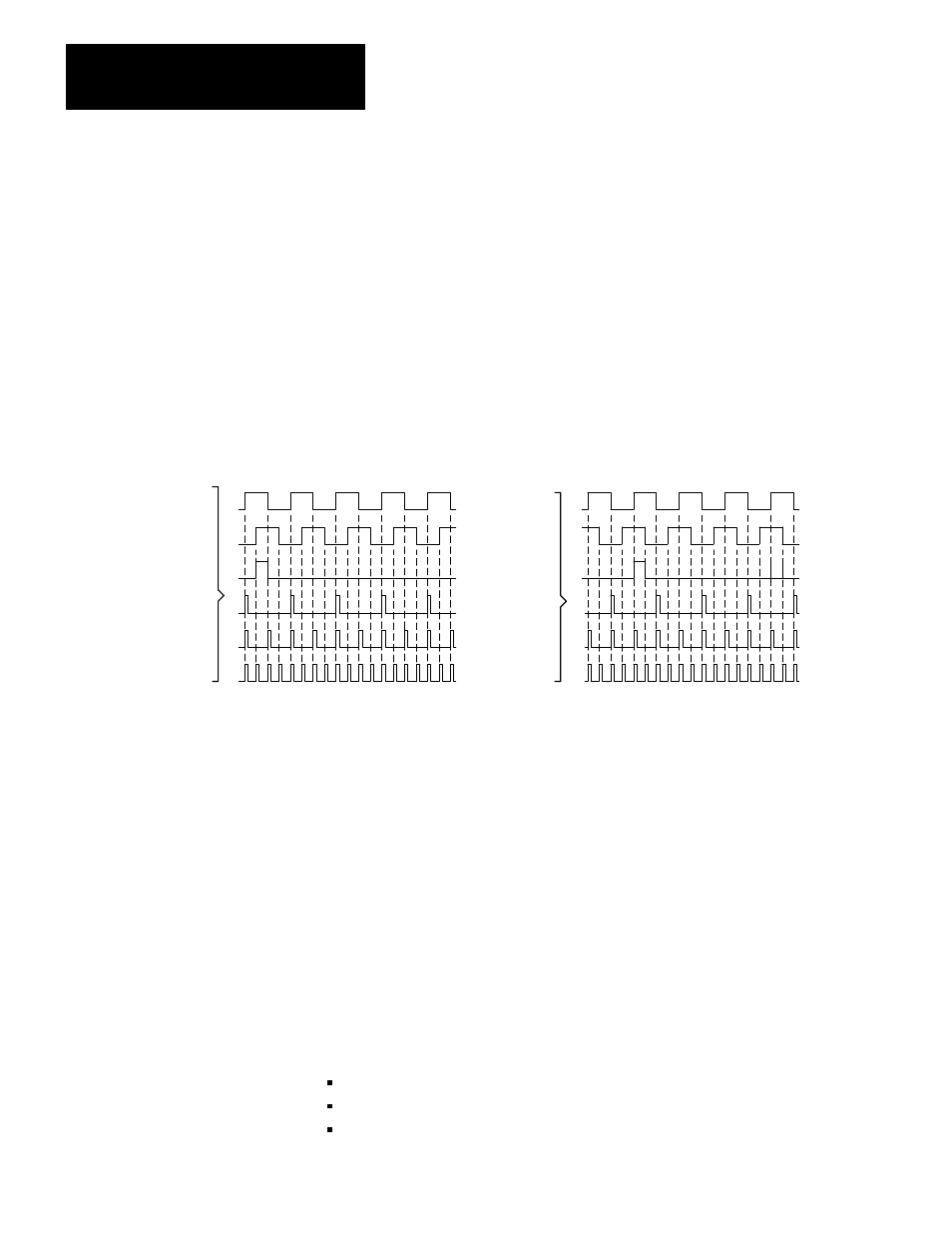
Channel Phase Relationship
The photodetectors are placed so that the channel A and channel B output
signals are out of phase by 90
o
(Figure 3.7). The lead/lag relationship of
these signals indicates the direction of axis motion. Also, the phase
relationship of these signals allow the decoding circuit to count either 1, 2,
or 4 feedback pulses for each line of the encoder (Figure 3.7). This
provides flexibility in establishing feedback resolution.
Figure 3.7
Encoder Signals Ć Showing Phase Relationship
Forward
Reverse
Channel A
Channel B
Marker
x1
x2
x4
Note: For the servo positioning assembly, the encoder
marker must be high when both channel A and channel
B are high, or the marker is not recognized unless you
set the marker logic jumper to the notĆgated position.
Channel A
Channel B
Marker
x1
x2
x4
11001
Feedback Resolution
The following discussion of feedback resolution assumes that you are
using a leadscrew, and that the encoder is coupled directly to the
leadscrew with no intermediate gearing. These assumptions apply to
many applications. If your application differs, be sure to account for the
differences.
Feedback resolution is the smallest axis movement the servo positioning
system can detect. It is determined by:
leadscrew pitch - axis displacement per revolution
encoder lines - number of lines per revolution
feedback multiplier - selected as x 1, x2, or x4