Keying – Rockwell Automation 1771-QC , D17716.5.25 SER/B SERVO POS User Manual
Page 57
Installing the Assembly
Chapter 6
6Ć7
With a differential encoder, the connections and the polarity jumper
positions determine the polarity of the feedback signals. With a
single-ended encoder, the polarity jumper positions alone determine the
polarity of the feedback signals.
The polarity selections are important to the marker logic. Set the polarity
so that the marker is true at the same time that channels A and B are true
(refer to Figure 3.7)
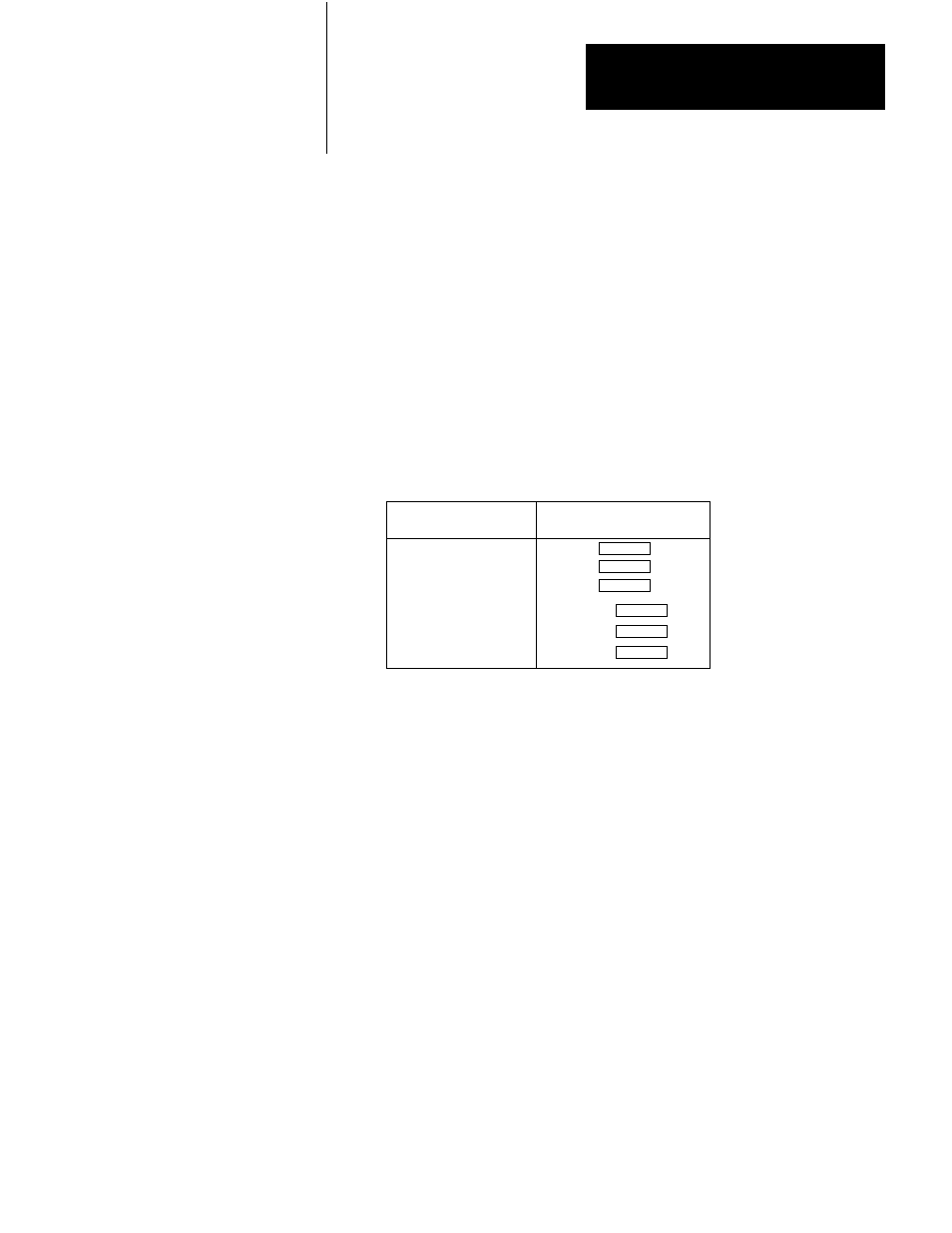
Selecting Encoder Input Signal Mode
Select the signal mode of each encoder input to match the encoder
(Figure 6.1).
Single-ended Left
Right
Differential
Encoder Signal Mode Jumper Position
•
•
•
•
•
•
Selecting Marker Logic
For almost all encoders, set the marker logic jumper to the bottom
position to gate the marker with channel A and channel B. This gives the
marker signal a level of noise immunity.
However, if you cannot select the polarity so that the marker on your
encoder is always true at the same time as the channel A and B signals, set
the market logic jumper to the top position.
A package of plastic Keys (cat. no. 1771-RK) is provided as standard with
each I/O chassis. When properly installed, these keys can guard against
the seating of all but a selected type of module in a particular I/O chassis
module slot. Keys also help align the module with the backplane
connector.
Keying