Recommendations for wiring your rtb, Wire terminations, Wire an allen-bradley 845 incremental encoder – Rockwell Automation 1756-HSC ControlLogix High Speed Counter Module User Manual
Page 47
Rockwell Automation Publication 1756-UM007C-EN-P - November 2011
Install and Wire the ControlLogix High-speed Counter Module
47
Recommendations for Wiring Your RTB
We recommend that you follow these guidelines when wiring your RTB.
1. Begin wiring the RTB at the bottom terminals and move up.
2. Use a tie to secure the wires in the strain relief (bottom) area of the RTB.
3. Order and use an extended-depth housing (catalog number 1756-TBE)
for applications that require heavy gauge wiring.
See
for cable considerations.
Wire Terminations
The following sections provide details about wiring terminations to specific
products.
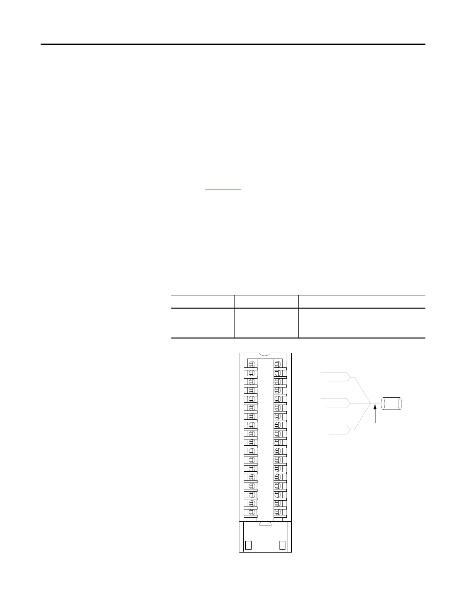
Wire an Allen-Bradley 845 Incremental Encoder
Use the table and diagram to connect the 1756-HSC module to an
Allen-Bradley 845 incremental encoder.
Application
A1 Connections
B1 Connections
Z1 Connections
Differential Line
Driver Output
(40 mA)
White - A1 5V DC
Black of white -
A1Return
Blue - B1 5V DC
Black of blue - B1
Return
Green - Z1 5V DC
Black of green - Z1
Return
Z1 (12…24V)
Z1 (5V)
Z1 (RET)
B1 (12…24V)
B1 (5V)
B1 (RET)
A1 (12…24V)
A1 (5V)
A1 (RET)
Not Used
Not Used
Not Used
Z0 (12…24V)
Z0 (5V)
Z0 (RET)
B0 (12…24V)
B0 (5V)
B0 (RET)
A0 (12…24V)
A0 (5V)
A0 (RET)
Not Used
Not Used
Not Used
COMMON 0
COMMON 0
COMMON 0
DC-0(+)
Out 2
Out 3
COMMON 1
COMMON 1
COMMON 1
DC-1(+)
Out 0
Out 1
Black
Black
White
Black
Blue
Green
Differential Line
Driver Output
41601
Allen-Bradley
Bulletin 845
Incremental
Encoder
2
4
6
8
10
12
14
16
18
20
22
24
26
28
30
32
34
36
1
3
5
7
9
11
13
15
17
19
21
23
25
27
29
31
33
35