Sample period for period/continuous rate modes – Rockwell Automation 1756-HSC ControlLogix High Speed Counter Module User Manual
Page 33
Rockwell Automation Publication 1756-UM007C-EN-P - November 2011
Frequency Modes
33
As the frequency of the incoming pulse train increases, the number of sampled
pulses from the 4 MHz clock decreases. Because accuracy is related to the
number of 4 MHz pulses received over the sample period, the accuracy will
decrease with increasing input frequencies at the Z-input. The decrease in
accuracy can be lessened by scaling the input frequency through the use of the
Scaler tag.
The Scaler configuration allows the incoming pulse train at the Z-input to be
divided by a user-defined number. The internal 4 MHz pulses are counted for
the duration of an input pulse, or multiple pulses if the Scaler is > 1. Measuring
multiple input periods increases the accuracy of your measurement.
Acceptable numbers for the scaler are 1, 2, 4, 8, 16, 32, 64, and 128. There is
one Scaler value for each counter. The default value for each Scaler is 1;
a 0 is equivalent to 1.
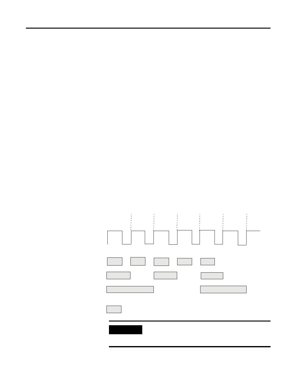
Sample Period for Period/Continuous Rate Modes
In Period and Continuous Rate modes, the Scaler value defines the number of
half-cycles of the incoming pulse train that comprises the sample period.
The 4 MHz count value in the Present Value tag is incremented within the
pulse train set by the Scaler tag.
The length of the sample period in time will vary with the incoming frequency.
The lower the incoming frequency, the longer the time.
1
2
3
4
5
6
Cycles
Input Pulses on Z-Input
Sample Period for Scaler of:
1 (*)
2
4
* - a 50% duty cycle is required for accurate Frequency calculations when using a scaler of 1.
4 MHz count value in Present Value tag is incremented.
44926
IMPORTANT
Sample period times scaler must be less than 0.25 seconds or
the counter will overflow without providing an overflow
indication.