Output circuits – Rockwell Automation 1756-HSC ControlLogix High Speed Counter Module User Manual
Page 112
Rockwell Automation Publication 1756-UM007C-EN-P - November 2011
112 Application Considerations
In either case, this example is similar to the Open Collector example and can
use the following equation assuming a 2.0V drop across D4 + Q2.
(Supply Voltage) - (V
drop
)
____________________ = Available current
R1 (if used) + (R2)
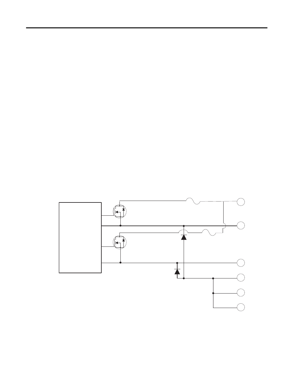
Output Circuits
The 1756-HSC module contains two isolated pairs of output circuits.
Customer supplied power, ranging from +5 to +24V DC, is connected
internally (through terminal Vcc) to the power output transistors. When an
output is turned on, current flows into the drain, out of the source, through
the fuse and into the load connected to the ground of the customer supply
(customer return). Diodes D5 and D6 protect the power output transistors
from damage due to inductive loads.
If local electrical codes permit, outputs can be connected to sink current. This
is done by connecting the load between the power supply + terminal and the
customer Vcc terminal on the field wiring arm. The output terminal is then
connected directly to ground (customer return). Note that this wiring method
does not provide inductive load protection for the power output transistors.
34
32
F2
30
D5
36
26
28
Customer
Vcc
D6
Out 0
Out 1
Customer
Return
F1
Drive
Circuit
Q14
G
D
S
Q15
G
D
S
Customer
Return
Customer
Return
44802