Electromechanical limit switch – Rockwell Automation 1756-HSC ControlLogix High Speed Counter Module User Manual
Page 111
Rockwell Automation Publication 1756-UM007C-EN-P - November 2011
Application Considerations
111
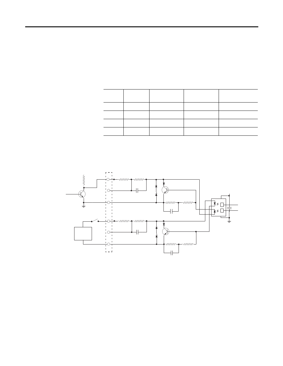
Choosing input terminals provides some options, as shown in the table. If we
assume a 2.0V drop across D1 + Q1, we can use the following equations to
calculate the available current:
(Supply Voltage) - (V
drop
)
_______________________ = Available current
(Pull-up) + R1 (if used) + (R2)
You must increase the supply voltage above 12V to make sure there is
sufficient input current to overcome the additional 2 k
pull-up impedance.
Keep in mind that you want the available current to be at least 4 mA.
Electromechanical Limit Switch
When using an electromechanical limit switch (the lower circuit in figure
above), it is recommended that you enable the input filter, using RSLogix 5000
software to filter out switch contact bounce. However, this limits the
frequency response to around 70 Hz. This circuit would be similar when using
DC proximity switches, but bounce should not occur unless severe mechanical
vibration is present.
Example Supply
Voltage
Input Terminal
Total Impedance Available Current
1
12
12 to 24V
3.15 k
3.1 mA (insufficient)
2
12
5V
2.15 k
4.6 mA (minimal)
3
24
12 to 24V
3.15 k
6.9 mA (optimal)
4
24
5V
2.15 k
10.2 mA (acceptable)
Input Terminals
14
16
18
13
15
17
R1
1K
R2
150
C1
R3
1K
R4
150
C2
D2
D3
D5
D6
R7
40.2
R8
40.2
D4
Q2
D1
Q1
R5
40.2
R6
40.2
C3
+5V
44801
+12V
2K
Output
Ground
Open Collector
Input
Limit Switch or
DC Proximity
Switch
+12 to 24V
Power
Supply
Switch
Ground