Examples for selecting input devices, Circuit overview – Rockwell Automation 1756-HSC ControlLogix High Speed Counter Module User Manual
Page 106
Rockwell Automation Publication 1756-UM007C-EN-P - November 2011
106 Application Considerations
Examples for Selecting
Input Devices
The following examples help you determine the best input type for your
particular application. These examples include:
• 5V differential line driver.
• single-ended driver.
• open collector circuit.
• electromechanical limit switch.
Circuit Overview
To make sure your signal source and the 1756-HSC module are compatible,
you need to understand the electrical characteristics of your output driver and
its interaction with the 1756-HSC input circuit.
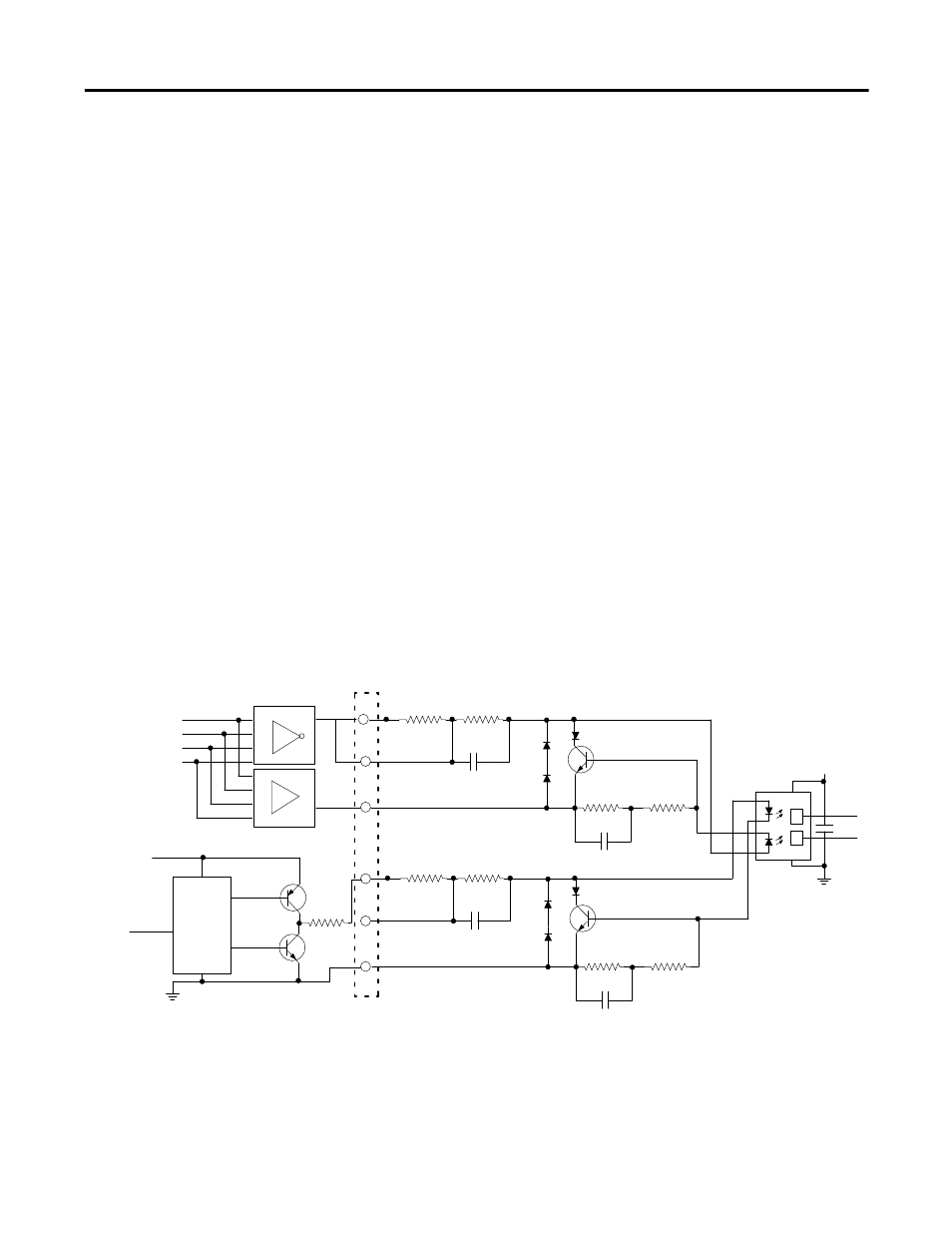
As shown in the illustration, the most basic circuit consists of R1, R2, the
photodiode and associated circuitry around half of the opto-isolator. The
resistors provide first-order current limiting to the photodiodes of the dual
high-speed opto-isolator. When a signal is applied to the 12-24V inputs (pins
13 and 17 in the graphic), the total limiting resistance is R1 + R2 = 1150 .
Assuming a 2V drop across the photodiode and R5 and R6, you would have
8-21 mA demanded from the driving circuit as the applied voltage ranged from
12 to 24V.
When a signal is applied to the 5V inputs (pins 15 and 16 in the graphic), the
limiting resistance is 150 . If 5.0V was applied at the input, the current
demanded would be (5.0 - 2.0)/150 = 20 mA.
42628
5V Differential
Line Driver
Input Terminals
14
16
18
13
15
17
R
22
High
Drive
Low
Drive
+12 to 24V
Input
+ 12 to 24V
Single-ended
Driver
R1
1K
R2
150
C1
R3
1K
R4
150
C2
D2
D3
D5
D6
R7
40.2
R8
40.2
D4
Q2
D1
Q1
R5
40.2
R6
40.2
C3