Period rate and continuous rate modes – Rockwell Automation 1756-HSC ControlLogix High Speed Counter Module User Manual
Page 32
Rockwell Automation Publication 1756-UM007C-EN-P - November 2011
32 Frequency Modes
Period Rate and
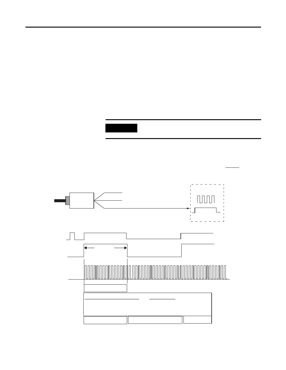
Continuous Rate Modes
These two Frequency-operational modes are identical in how they calculate
frequency. They determine the frequency of input pulses by counting the
number of internal 4 MHz clock pulses over a user-specified number of
Z-input signal pulses defined by the Scaler.
Frequency = .5 x Scaler / 250 ns x 4 MHz pulses
At the end of the sample period, the module returns the frequency in the
Stored Value tag, the number of internal 4 MHz pulses in the
Present Value tag, and a value indicating the total number of Z-input pulses
that have occurred in the Totalizer tag. The output On/Off values are related
to the value in the Present Value tag.
The difference between these two modes is in the operation of the outputs. In
Continuous Rate mode, outputs are dynamically checked against their
configured presets. In Period Rate mode, outputs are checked only against
their configured presets at the end of the sample period. See
for details.
Period Rate / Continuous Rate Modes
IMPORTANT
Preset and rollover settings are not active in Period
Rate/Continuous Rate modes and must be equal to zero.
Encoder/Pulse Generator
Z Input
A Input Not Used
B Input Not Used
1756-HSC Module
From Internal
4 MHz Clock
Scaler Value = 1
100 ms
No. of Sampled Pulses
41684
1, 2, 3 ....................400,000
4 MHz Internal Clock
No. of 4 MHz Pulses
in Present Value Tag
Frequency in Stored Value Tag
.5 x Scaler*
250 ns ** x No. of 4 MHz clock
=
.5
250 ns x 400,000
=
5 Hz
* If the scaler is equal to 1, the Frequency is accurate only if the duty cycle is 50%.
** One 4 MHz pulse = 250 ns.
Incoming Pulse
Train at Z-Input
...9
10
11
9
10
. . .
Totalizer Tag
Determined by
Scaler No. of
Z-Input Pulses