Troubleshooting 10-3 – Rockwell Automation 1557 MEDIUM VOLTAGE AC DRIVE User Manual
Page 245
TROUBLESHOOTING
10-3
1557-UM050F-EN-P – June 2013
Line Side Control Board Replacement
The following procedure must be followed when the Line Side Drive Control Board (80165-018-51) is
replaced.
1. Record the drive setup: A) complete parameter list, B) fault masks, C) fault messages, and D) PLC
links. This should be done on a drive commissioning form or with the use of the door mounted drive
printer (if the drive has this option). If this information can not be accessed from the drive due to a
severely damaged Line board this information should be available from the customers copy of the
commissioning form.
CAUTION: The CMOS devices used on the control circuit boards can be
destroyed or damaged by static charges. If personnel will be working
near static sensitive devices, they must be appropriately grounded.
2. Isolate the drive from medium voltage incoming line. Power down the drive control power, replace the
Line Side control board. The Firmware chips located in U12 and U13 must be on the same Rev. level
as the firmware located in the Machine Side control board. If the firmware is not identical or is not
present (replacement boards are not supplied with firmware) remove the firmware from the old board
and install it in the new board, insuring that the orientation and the location of the chips are correct.
3. Power up the drive control power, both green Healthy LEDs should illuminate and stay illuminated with
no flicker.
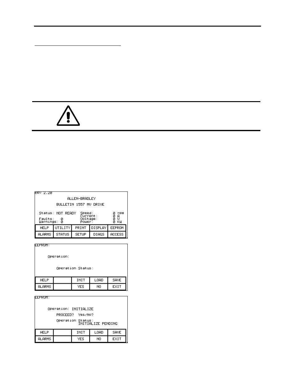
4. From the main screen press function key F5
(EEPROM).
5. Press function key F3 (INIT). If nothing
happens when you press F3, you do not have
unrestricted access. Return to the main menu,
go to the access screen, and enter the
password to enable this function.
6. Press function key F8 (YES). The drive control
will initialize to the default parameters.