18 commissioning – Rockwell Automation 1557 MEDIUM VOLTAGE AC DRIVE User Manual
Page 218
9-18
COMMISSIONING
1557-UM050F-EN-P – June 2013
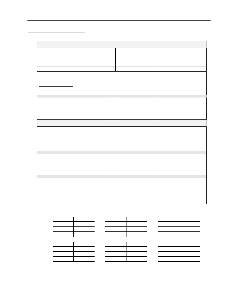
Inverter Power Supply Readings
800 / 1500 AMP G.T.O.
BOARD COMBINATIONS
POSITIVE RAIL
TP5 to TP15
NEGATIVE RAIL
TP3 to TP15
80165-178-51 with 80165-138-53/54
+7.5V to +8.8V
-12.45V to -12.55V
80165-698-51 with 80165-138-53
+7.5V to +9.0V
-12.45V to -12.55V
80165-698-51 with 80165-138-54
+7.5V to +10.0V
-12.45V to -12.55V
NOTE: Adjust the voltage at TP3 first and then verify that the voltage at TP5 is within the range
described.
Voltage Drift Limits
The maximum allowable drift range for the positive rail is between+10.0V and +7.0V
The maximum allowable drift range for the negative rail is between -15.0V and -11.5V
BOARD COMBINATIONS
80165-958-51 with 80190-058-51/52
NOTE: Self-calibrating no adjustment
required. Verify voltage values only.
POSITIVE RAIL
TP20 to TP32
+8.60 to +9.40
NEGATIVE RAIL
TP16 to TP32
-12.10 to -12.90
3000 AMP G.T.O.
BOARD COMBINATION
80165-958-53 with 80165-978-53
NOTE: Self-calibrating no adjustment
required. Verify voltage values only.
POSITIVE RAIL
TP17 to TP18
+12.50V to +13.50V
TP10 to TP5
+7.80V to +8.20V
NEGATIVE RAIL
TP13 to TP5
-19.70V to -20.30V
BOARD COMBINATION
80165-958-53 with 80190-058-53
NOTE: Self-calibrating no adjustment
required. Verify voltage values only.
POSITIVE RAIL
TP20 to TP32
+12.60 to +13.40
NEGATIVE RAIL
TP16 to TP32
-19.60 to -20.40
BOARD COMBINATION
80165-178-51 with 80165-758-53
NOTE: Adjust the voltage at TP13 first and
then verify that the voltage at TP19 is
within the range described.
POSITIVE RAIL
TP19 to TP16
+11.40V to +12.60V
NEGATIVE RAIL
TP13 to TP16
-19.90V to -20.10V
1a
3a
5a
1b
3b
5b
1c
3c
5c
1d
3d
5d
4a
6a
2a
4b
6b
2b
4c
6c
2c
4d
6d
2d