Enabling the adapter to receive peer i/o, Figure b.3 receiving i/o from a peer device – Rockwell Automation 1336-GM6 Enhanced DeviceNet Communications Module User Manual
Page 95
Enhanced DeviceNet Adapter’s Parameters
B-7
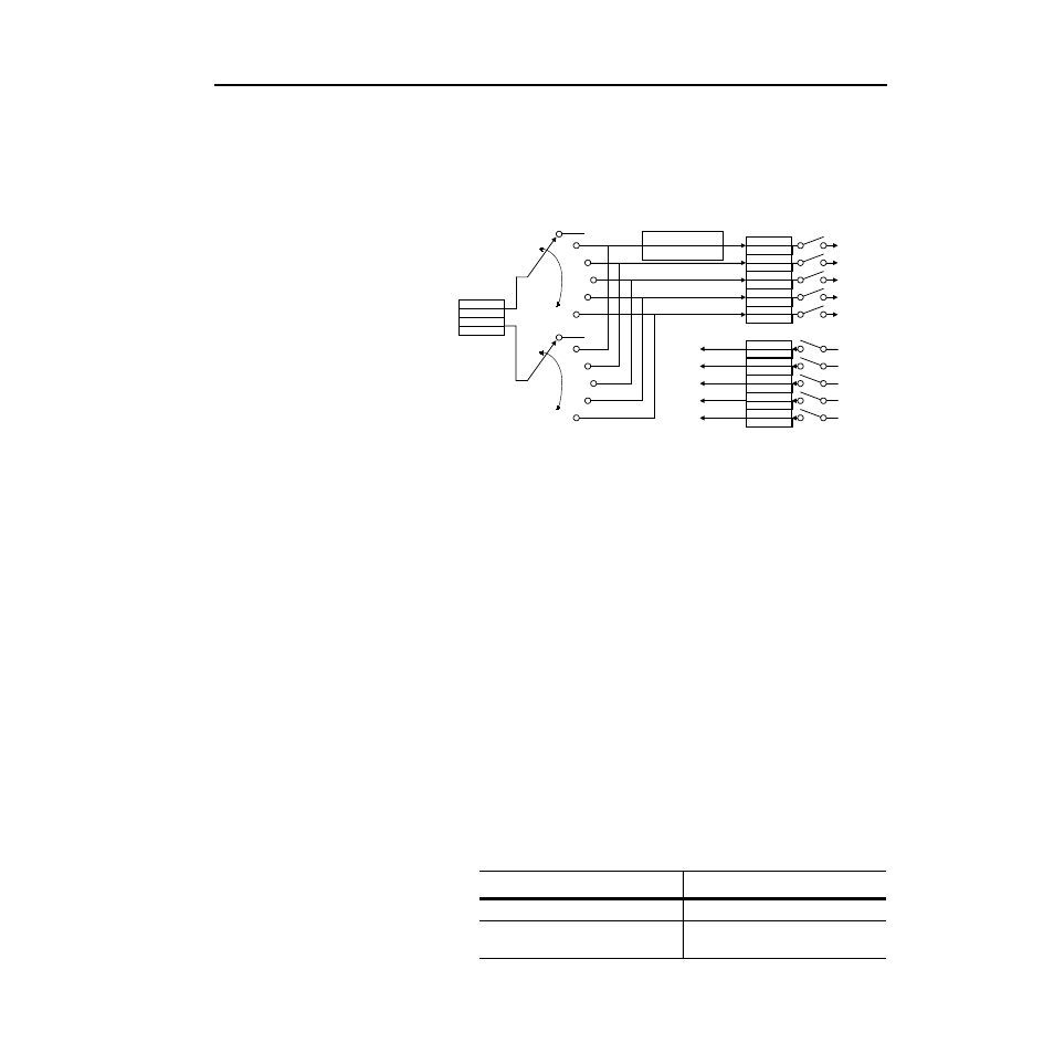
Enabling the Adapter to Receive Peer I/O
To have your Enhanced DeviceNet adapter receive input data from
another Enhanced DeviceNet adapter on the network, you must
configure it for peer-to-peer communications.
Figure B.3
Receiving I/O from a Peer Device
In Peer-to-Peer communications, you can receive 2 or 4 I/O words
from another adapter. Follow these directions:
1. Enable the desired I/O and datalinks within the adapter and
SCANport product. Refer to the Using Datalinks and Command
I/O section in this chapter.
2. Ensure the Peer Inp Enable (36) parameter is Off.
3. Set the Peer Node to Inp (34) parameter to the number of the node
from which you want to receive data.
4. Set the Peer A Input (29) parameter to a destination for the first 2
words of data.
5. If using 4 words of input, set the Peer B Input (30) parameter to a
destination for the second two words of data.
6. If receiving Cmd/Ref input data, set the bits in the Peer Cmd
Mask (31) parameter according to the following table.
Important: If both Master-Slave data and Peer data are being used to
control the adapter, make sure you know which one is transmitting
which control bits. The adapter will receive each control bit from only
one source. This includes the stop bit.
Reference
Logic Command
DL A2 Inp
DL A1 Inp
DL B2 Inp
DL B1 Inp
DL C2 Inp
DL C1 Inp
DL D2 Inp
DL D1 Inp
Feedback
Logic Status
DL A2 Out
DL A1 Out
DL B2 Out
DL B1 Out
DL C2 Out
DL C1 Out
DL D2 Out
DL D1 Out
Module Input
Module Output
Data to the
SCANport
Device
Data from the
SCANport
Device
Peer Input
Data from
DeviceNet
Peer A Word 2
Peer A Word 1
Peer B Word 2
Peer B Word 1
Peer A Input
Peer B Input
Peer Ref Adjust
Peer Cmd Mask
If receiving I/O from:
Then set bit to:
Master device (PLC or SLC)
0
Peer device (another Enhanced
DeviceNet adapter)
1