Hardware and parts description, Hardware and parts description -5 – Rockwell Automation 1336-GM6 Enhanced DeviceNet Communications Module User Manual
Page 17
Overview
1-5
Hardware and Parts Description
The hardware included with the adapter depends on the adapter that
you have.
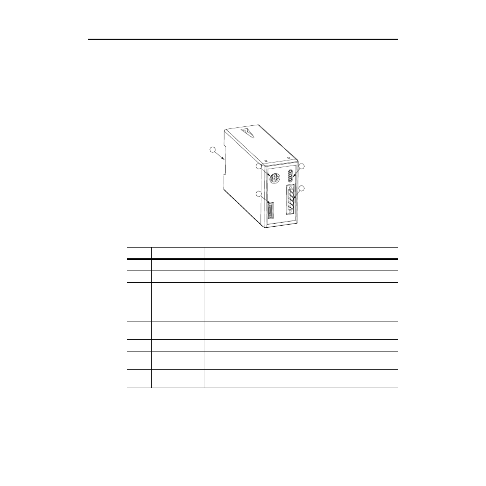
1203-GU6 Module Hardware
Figure 1.3 illustrates and the following table lists the main parts of the
1203-GU6 Enhanced DeviceNet communications module:
Figure 1.3
Parts of the 1203-GU6 Module
2
3
4
5
1
Number
Part
Description
1
DIN Rail Mount
Securely attaches and electronically grounds the module to the DIN rail.
2
SCANport Connection
Provides a standard SCANport 8-pin circular mini-DIN connector for the SCANport cable.
3
RS-232 Serial Port
Provides a connection for terminals capable of RS-232 serial communications. This port can
be used to edit the module’s parameters, download a file needed to perform a flash to the
module’s operating code, and support devices that monitor and test the module. A 1203-SFC
serial cable and a PC running a terminal emulation program or a VT100-compatible terminal
are required to use this port.
4
Bi-Color LEDs
Indicate the status of the DeviceNet media channel, of the SCANport connection, and of the
module. For more information, refer to Chapter 8, Troubleshooting.
5
DeviceNet Connection
Provides a 5-pin Phoenix connector to attach the module to the network.
Not
shown
5-Pin Plug-In
Connector
This part is supplied with the module. The 5-pin plug-in connector (P/N 22112-215-01) is a
connector to attach to the cable.
Not
shown
10-Pin Plug-In
Connector
This part is supplied with the module. The 10-pin plug-in connector (P/N 94220605) is a
connector to attach to the cable.