Slc ladder logic program example – Rockwell Automation 1336-GM6 Enhanced DeviceNet Communications Module User Manual
Page 69
Ladder Logic Programming
6-7
SLC Ladder Logic Program Example
The following example uses a SLC-5/03, a 1747-SDN DeviceNet
scanner, and a 1203-GU6 to control a 1336 PLUS, 1336 PLUS II or
1305 drive.
The example assumes that there is an operator’s station wired to an
I/O module in slot one of module group zero of rack zero.
Important: You may want to verify a device has not failed using
word I:S.0. If a device has failed, read the appropriate M1 File to find
out which device failed. Refer to the 1747-SDN DeviceNet Scanner
Module Manual, Publication 1747-5.8, for more information.
Figure 6.3
Example SLC Ladder Logic Program
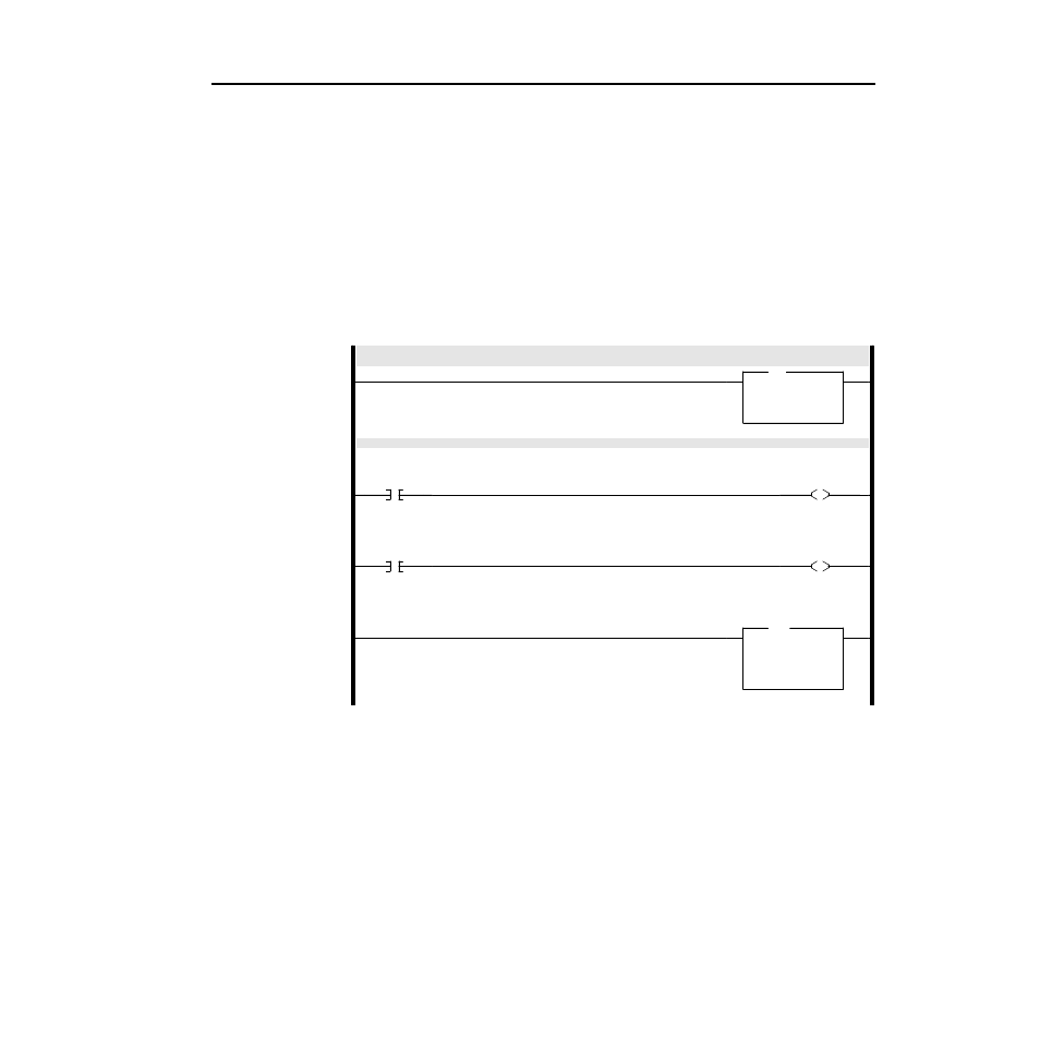
The scanner gathers drive status information via DeviceNet.
The M-File is copied into the SLC’s N9 data file to move the drive status information into a convenient location.
0000
COP
Copy File
Source
#M1:1.0
Dest
#N9:0
Length
128
COP
Rungs 0001 through 0003 move the drive status from the N9 data file to an operator display.
0001
N9:0
1
1336PLUS
RUNNING
Status Bit
O:3.0
0
1746-O*8
Operator Display
Drive Running
Status Bit
0002
N9:0
7
1336PLUS
FAULTED
Status Bit
O:3.0
1
1746-O*8
Operator Display
Drive Faulted
Status Bit
0003
MOV
Move
Source
N9:1
0<
Dest
N21:1
0<
MOV
Operator Display
Drive Frequency Feedback