Rockwell Automation 1336-GM6 Enhanced DeviceNet Communications Module User Manual
Page 58
5-4
Configuring a Scanner to Communicate with the Adapter
Figure 5.5
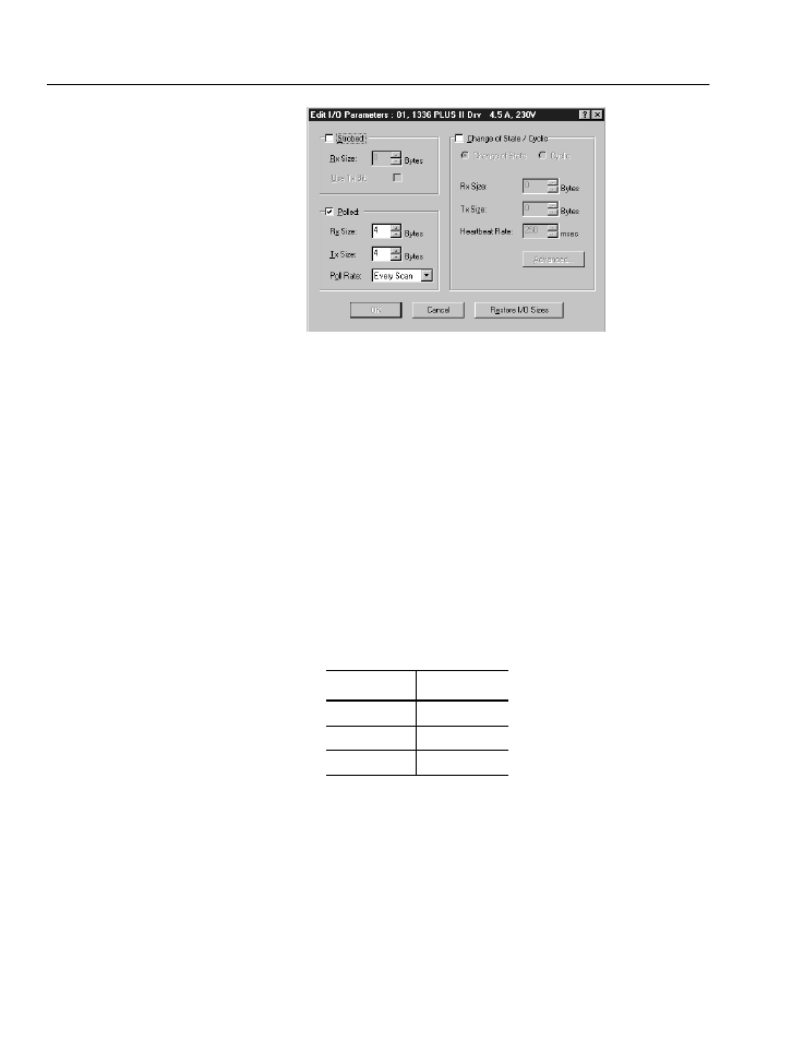
Edit I/O Parameters Dialog Box
9. Select the type(s) of data exchange (Polled, Change of State,
and/or Cyclic). In our example, we selected Polled.
10. Type the number of bytes that will be required for your I/O in the
Rx Size and Tx Size. The size will depend on the I/O that you
enabled in the adapter. The I/O is set using the Cmd/Stat Config
(Parameter 4) and the Datalink x Cfg (Parameters 5 – 8) in the
adapter.
In our example, we typed 4 in the Rx Size and Tx Size boxes
because we have enabled only the Cmd/Stat Config (Parameter 4)
for I/O in the adapter. In the Output image, our product uses one
16-bit word for the logic command and one 16-bit word for the
reference. A 16-bit word is two bytes. In the Input image, our
product uses one 16-bit word for logic status and one 16-bit word
for feedback. Therefore, the logic command/status uses 2 bytes
and the reference/feedback uses 2 bytes, totaling 4 bytes.
11. Set the scan rate:
Click Help for more information.
12. Click OK. If you changed any settings, a Scanner Applet appears
and asks if it is OK to unmap the I/O. Click Yes to continue. The
Edit I/O Parameters dialog box closes and then the Scanner
Module dialog box (Figure 5.4) reappears. You will map the I/O
in the next section in this chapter.
Data Exchange
Rate to set
Polled
Polled Rate
Change of State
Heartbeat Rate
Cyclic
Send Rate