What are ladder logic programs, What are ladder logic programs? -2 – Rockwell Automation 1336-GM6 Enhanced DeviceNet Communications Module User Manual
Page 64
6-2
Ladder Logic Programming
For more information on RSLogix5 or RSLogix500, consult the
respective software’s documentation.
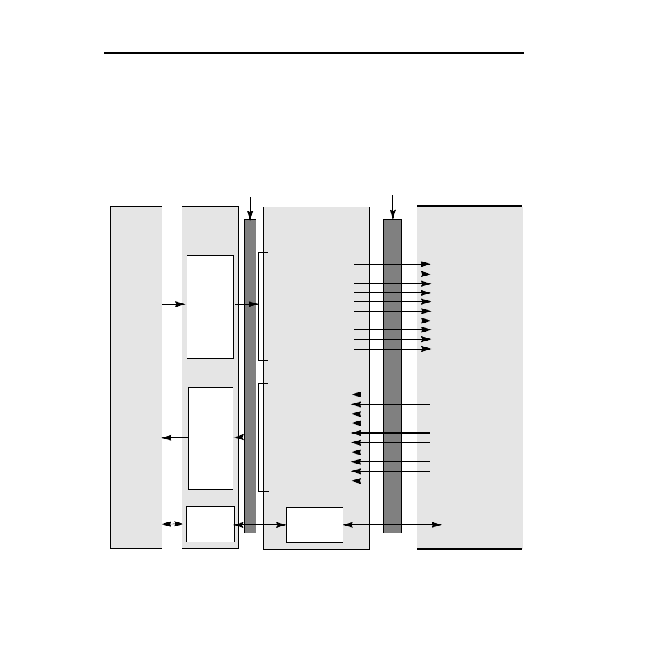
What are Ladder Logic Programs?
A PLC or SLC ladder logic program lets you control the drive and the
messaging from the PLC or SLC to the drive. Figure 6.1 shows how
the I/O image table for a DeviceNet scanner relates to a drive, such as
a 1336 PLUS drive, when an Enhanced DeviceNet communications
adapter is used. Note that the location of the first word (n) depends on
the I/O mapping.
Figure 6.1
I/O Image Table
Important: Datalinks are optionally enabled in the adapter and configured in the product. Refer to
Chapter 3, Configuring the 1203-GU6 Enhanced DeviceNet Module Using a Serial Connection or
Chapter 4, Configuring the Enhanced DeviceNet Adapter Using RSNetWorx for DeviceNet and your
product’s user manual for more information. Examples of reference/feedback include speed, torque,
and frequency.
1203-Gx6/1336-GM6
Enhanced DeviceNet
Word 0 Logic Command
Word 1 Reference
Word 2 Datalink A1
Word 3 Datalink A2
Word 4 Datalink B1
Word 5 Datalink B2
Word 6 Datalink C1
Word 7 Datalink C2
Word 8 Datalink D1
Word 9 Datalink D2
Logic Status
Feedback
Data Out A1
Data Out A2
Data Out B1
Data Out B2
Data Out C1
Data Out C2
Data Out D1
Data Out D2
Drive
PLC,
SLC,
PC
SCANport
Output
Mapping
(Write)
Message
Handller
Scanner
Input
Mapping
(Read)
Logic Command
Reference
Data In A1
Data In A2
Data In B1
Data In B2
Data In C1
Data In C2
Data In D1
Data In D2
Word 0 Logic Status
Word 1 Feedback
Word 2Datalink A1
Word 3 Datalink A2
Word 4 Datalink B1
Word 5 Datalink B2
Word 6 Datalink C1
Word 7 Datalink C2
Word 8 Datalink D1
Word 9 Datalink D2
Message
Buffers
Message Handler
DeviceNet