Rockwell Automation 1336-GM6 Enhanced DeviceNet Communications Module User Manual
Page 18
1-6
Overview
1336-GM6 Board Hardware
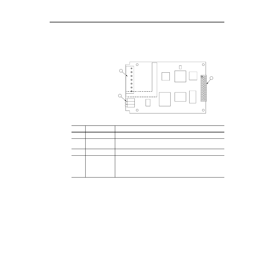
Figure 1.4 illustrates and the following table lists the main parts of the
1336-GM6 Enhanced DeviceNet communications board:
Figure 1.4
Parts of the 1336-GM6 Board
1336-GM6 Board
1
2
3
Number
Part
Description
1
DeviceNet Connection
Provides a 5-pin Phoenix connector to attach the module to the DeviceNet network.
2
Bi-Color LEDs
Indicate the status of the DeviceNet media channel, of the SCANport connection, and of the
module. For more information, refer to Chapter 8,
Troubleshooting
.
3
SCANport Connection
Provides a 14-pin connector containing power and SCANport communication circuitry.
Not
Shown
Kit
Provides the necessary materials for mounting the board to the SCANport product. These
materials include one grounding wrist strap (P/N 22803-016-01), four Phillips mounting
screws (P/N 28159-036-26), four stand-off nylon headers (P/N 22805-030-01), one 5-pin
connector (P/N 22112-215-01), and one snap-in comm housing (P/N 188578) with mounting
instructions (P/N 189572).