Rockwell Automation 1336-GM6 Enhanced DeviceNet Communications Module User Manual
Page 23
Installation
2-3
Installing the 1203-GU6 Communications Module
The following instructions explain how to physically install your
Enhanced DeviceNet 1203-GU6 communications module.
1. Hook the top lip of the module’s DIN rail mount onto the top of
the DIN rail and then rotate the module onto the DIN rail. You
will hear the module snap into a locked position.
Figure 2.1
Mounting the Module onto the DIN Rail
2. Remove power from the network.
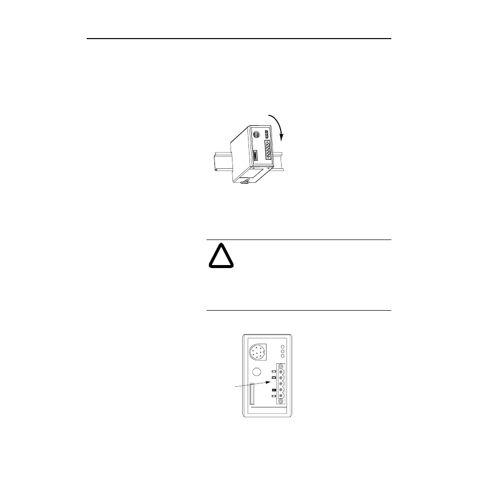
3. Insert the DeviceNet cable wires into the desired connector. Make
sure you follow the color key next to the connector receptacle on
the module.
Figure 2.2
Inserting DeviceNet Cable Wires into the Connector
!
ATTENTION: If you wire the 5-pin or 10-pin header
after you’ve connected it to the module, static control
precautions are required. Device malfunction may occur
if you do not follow ESD control procedures. If you are
not familiar with static control procedures, refer to
Allen-Bradley Publication 8000-4.5.2, Guarding
Against Electrostatic Damage, or other applicable ESD
protection handbook.
SCANport
SP
Mod
Net
Serial
DeviceNet
Allen-Bradley
1-Red- V+
2-White-CAN_H
3-Shield
4-Blue-CAN_L
5-Black- V-
Color Key