Led indicators, Firmware location – Rockwell Automation 1395 Multi-Comm Hardware/Software User Manual
Page 9
Chapter 2
Introduction and Product Description
2–2
!
ATTENTION: Certain procedures in this manual require that
the drive “Not be running”. This assumes that the DC loop
contactor is de-energized and that the user has properly set up
the interface logic to meet this criteria.
Additional hardware allows for a separate discrete input to the Drive. The
input device (Pushbutton, selector switch, etc) is connected to terminal
block J5 and is jumper selectable (see table 2–A) for either a 115V AC or
24V DC input. The function and operation of this input is controlled by
parameter settings.
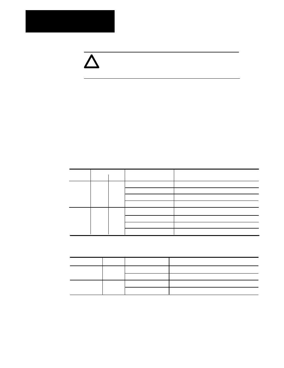
LED Indicators
The MCA board contains several LED’s used to provide status
information. LED DS1 indicates wheter the MCA board itself is faulted or
not faulted. LED’s DS2 and DS3 duplicate the function provided by the
LED’s on the Interface Plug. LED DS4 indicates the status of the Discrete
input. Tables 2–A and 2–B provide information on LED’s DS1 – DS4.
LED
State
DS2
Table 2-A.
LED Indicator Status for RIO and DH+ Communication
LED Green
LED Off
LED Blinking Green
LED Blinking Red
ChA
ChB
DS3
Function
Normal PLC Communications
No communication to PLC Controller
PLC is in Reset/Program/Test Mode
PLC Has Rack Inhibited
DS2
DS3
LED Yellow
LED Off
LED Blinking Yellow
LED Blinking Red
Normal DH+ Communications
MCA Board Faulted
No Communication over DH+
Duplicate Node Address on DH+ Link
RIO
DH+
LED
State
DS1
Table 2-B.
LED Indicator Status for Board and Discrete Input
LED Green
LED Off
Function
Normal Adapter Operation
Adapter is Faulted
DS4
LED Off
LED Green
Discrete input is Low
Discrete input is High
MCA Board
Status
Discrete Input
Status
Firmware Location
The MCA Board contains a microprocessor (U20) which is responsible for
controlling all board functions and features. This board contains firmware
version 1.xx (the “xx” designator may vary but does not affect information
in this manual). Figure 2–1 shows the physical location of the firmware
chip (UMA1). The setup and configuration data for the Adapter board is
stored in the EEPROM memory located on the main control board of the
Drive.