Figure 3-1. mca board overview – Rockwell Automation 1395 Multi-Comm Hardware/Software User Manual
Page 14
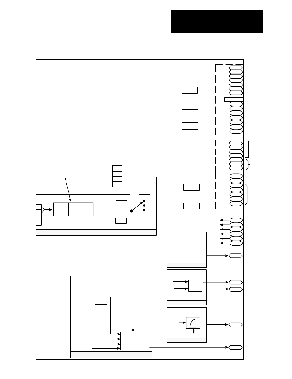
Chapter 3
Configuration & Interfacing
3–3
Figure 3-1. MCA Board Overview
Multiply #1 Block
ADD Block
TB
300
301
302
303
304
305
306
Channel A
DC Status
350
351
352
353
354
355
356
307
308
309
310
311
312
313
Channel B
CA Indirects
364
365
366
367
368
369
1
2
3
4
5
6
315
Multiply 1 Output
Multiply #2 Block
Filter Block
318
Add Output
317
Multiply 2
Whole Output
316
Multiply 2
Fractional
Output
319
Filter Output
I
1
xI
2
I
1
I
2
Par 504 x 505 x 517
Par 506
Par 507
515
Filter
Input
516 Filter Gain
R
1
+ R
2
+ R
3
+ C
4
R
1
Function Block
Overflow Par 517
Par 508 x 509
R
2
Par 510 x 511
R
3
Par 512 x 513
Offset
Par 514
C
4
Discrete Input
1
2
Position
1–2
2–3
24V DC Input
115V AC Input
Firmware
Version #
549
1
2
3
4
550
551
552
553
Constant
Parameters
Channel A
PLC Parameters
Channel A
DIP Switch Settings
523
RIO Fault Select
525
RIO Redundant
Channel #
526
(Available only
when redundant
RIO is selected via
DIP Switch)
Channel B
DH+ Parameters
524
3
4
545
DH+ FAULT SELECT
519
Bit Specifier
520
Operator
300
Parameter
518
314
See Figure 3–2
CHANNEL B
DIP SWITCH
SETTINGS
357
358
359
360
361
362
363
Global
Data
PCCC
Message
Global
Data
PCCC
Message
517
- 20P PowerFlex DC Drive - Frame D Bimetal Thermostat (10 pages)
- 1336S_F_T_E_R F Frame Snubber Resistor Repl. (6 pages)
- 22-COMM PowerFlex 4-Class DSI (Drive Serial Interface) Network Communication Adapter (4 pages)
- 8-545 Plug In Solid State Relay (2 pages)
- 20-HIM-B1 PowerFlex 7-Class HIM Bezel (DPI) (4 pages)
- 100 Contactors with DC Coil (1 page)
- 100 Contactors with DC Coil (2 pages)
- 20P PowerFlex DC Drive - Frame D Switching Power Supply Circuit Board (6 pages)
- 140G-MTFx_MTHx_MTIx_MTKx Trip Unit Installation-140G-M (6 pages)
- 45BRD Analog Laser Sensor (4 pages)
- 20D Multi-Device Interface Option Board for PowerFlex 700S Drives (20 pages)
- 56RF RFID 18 mm Cylindrical Transceiver (2 pages)
- 42KC Miniature Rectangular: 5V DC Version (2 pages)
- 20P PowerFlex DC Drive - Frame A Switching Power Supply Circuit Board (16 pages)
- 21P-MISC-A-TP-2 Transition Tube Kit #C19-6/7 For PowerFlex 755 w/OEM Liquid Cooling Fr 6/7 Drive (2 pages)
- 42BT Background Suppression Sensor (3 pages)
- 42CB High Speed 18mm Cylindrical (4 pages)
- 140EX-JE2_JE3 Molded Case Circuit Breaker (4 pages)
- 140G-K-EAM1A Early Make Aux Contact for Rotary Handle Oper Mech-140G-K (1 page)
- 140G-K-EAM1A Early Make Aux Contact for Rotary Handle Oper Mech-140G-K (3 pages)
- 20-HIM-A6 PowerFlex (Human Interface Module) (74 pages)
- 42CF General Purpose 12mm Cylindrical (4 pages)
- 20D PowerFlex 700S Phase II Drive Frames 1...6 (80 pages)
- 140EX-HE1_HE2 Molded Case Circuit Breaker (6 pages)
- 140EX-HE1_HE2 Molded Case Circuit Breaker (4 pages)
- 20B PowerFlex 700 Custom Firmware - Pump Off (12 pages)
- 20-WIM-N4S DPI Wireless Interface Module (92 pages)
- 140U H-Frame Circuit Breaker Fixed and Adjustable Thermal Trip (7 pages)
- 140U H-Frame Circuit Breaker Fixed and Adjustable Thermal Trip (2 pages)
- 60-2619, 42JS Swivel/Tilt Mounting Bracket (1 page)
- 22A PowerFlex 4/40/400 Flange Mount (4 pages)
- 45MLA Controller Installation Instructions (16 pages)
- 20P PowerFlex DC Drive - Cooling Fan for Frame A Drives Above 73A at 230V 460V AC (6 pages)
- 42JS Series 7000 to 42JS VisiSight Replacement Kit (2 pages)
- 22A PowerFlex 4-Class HIM Bezel (DSI) (4 pages)
- 42CS Stainless Steel Photoelectric Sensors (4 pages)
- 20L-LL PowerFlex 700L Liquid-to-Liquid Heat Exchanger (40 pages)
- 20P PowerFlex DC Drive - Frame B SCR Modules (20 pages)
- 22B PowerFlex 40 Quick Start FRN 5.xx - 6.xx (161 pages)
- 22B PowerFlex 40 Quick Start FRN 5.xx - 6.xx (22 pages)
- 22F PowerFlex 4M Input RFI Filters (2 pages)
- 45LFM Capacitive Label Sensor (4 pages)
- 140G-Rx Installation Instruction-140G-R (2 pages)
- 140G-Rx Installation Instruction-140G-R (29 pages)
- 22C PowerFlex 400 AC Drive Quick Start - FRN 1-4.xx (28 pages)