Rockwell Automation 1395 Multi-Comm Hardware/Software User Manual
Page 74
Chapter 3
Configuration & Interfacing
3–63
Day (1 – 31) – An integer value representing the day the trigger condition
was detected.
Hour (0 – 23) – An integer value representing the hour the trigger
condition was detected.
Second (0 – 59) – An integer value representing the second the trigger
condition was detected.
Millisecond – An integer value representing the 10’s of milliseconds in
which the trigger condition was detected.
Monitored Parameter Descriptor – An integer value used by
Allen-Bradley program terminals to display the proper units for the
monitored parameter.
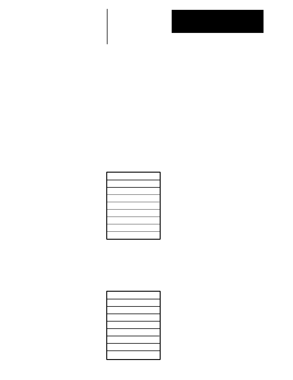
Block #1: This Block contains data samples 0 through 33 for the trend
buffer specified in the BTW instruction.
BTR Instruction Length: 38 words
MSG Size in Elements: 38
BTR
Data Samples – The data samples are
specified in Drive Units and may need to
be scaled by the PLC Controller prior to
being used in the Program.
0
0
270
See Note
1
Data Sample #1
Data Sample #2
•
Data Sample #33
Block #2: This Block contains data samples 34 through 66 for the trend
buffer specified in the BTW instruction.
BTR Instruction Length: 38 words
MSG Size in Elements: 38
BTR
Data Samples – The data samples are
specified in Drive Units and may need to
be scaled by the PLC Controller prior to
being used in the Program.
0
0
270
See Note
2
Data Sample #34
Data Sample #35
•
Data Sample #36