Discrete plc controller i/o data transfer – Rockwell Automation 1395 Multi-Comm Hardware/Software User Manual
Page 26
Chapter 3
Configuration & Interfacing
3–15
Discrete PLC Controller
Data required by the Drive on a continuously updated basis is transferred
I/O Data Transfer
using the I/O image table of the PLC Controller. The data transfer rate can
be determined using the standard conventions for I/O rack updates of
discrete I/O. Refer to the PLC Controller manual for details.
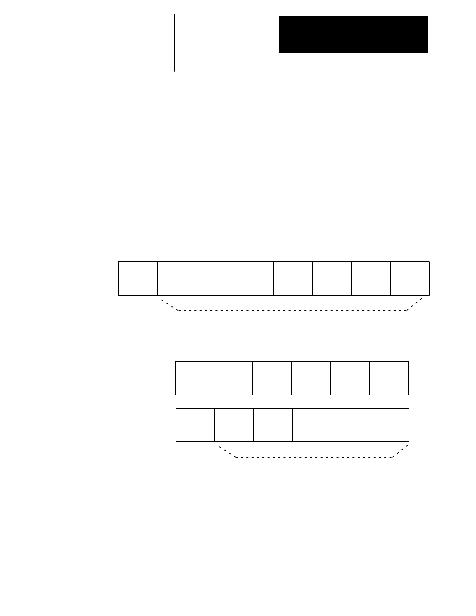
Refer to Figures 3–9 thru 3–11. These figures indicate how data is
transferred between the Drive and PLC controller for the rack size selected.
The first group number associated with a rack is reserved for the block
transfer function. The remainder of group numbers (1–7 for full racks, 1–5
or 3–7 for 3/4 racks, 1–3 or 5–7 for half racks) are used for the transfer of
discrete type data. Each group number reserves a single 16 bit word in both
the input and output image table of the PLC Controller for the rack number
assigned. In the Drive these words are directly linked to internal Drive
parameters using source and sink parameters as shown in Figure 3–12.
Figure 3-9. RIO Full Rack Configuration
Group 0
Groups 1–7 each appear (to the PLC Controller) to
have a 16 bit input and output module installed.
Group 1
Group 2
Group 3
Group 4
Group 5
Group 6
Group 7
Reserved
for Block
Transfer
Figure 3-10. RIO 3/4 Rack Configuration
Group 0
Group 1
Group 2
Group 3
Group 4
Group 5
Group 2
Each group appears to have a 16 bit input
and output module installed.
Group 3
Group 4
Group 5
Group 6
Group 7
Reserved
for Block
Transfer
Configured as 3/4 Lower Rack
Configured as 3/4 Upper Rack