Rockwell Automation 1395 Multi-Comm Hardware/Software User Manual
Page 31
Chapter 3
Configuration & Interfacing
3–20
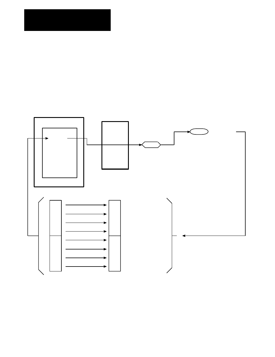
Bit numbering in the PLC Controller is performed in Octal, as opposed to
Decimal numbering in the Drive parameter 150, so it is necessary to relate
the output image table bits to the controlled bits in parameter 150. Figure
3–15 shows the correlation between the output image table bits and the
Drive parameter 150 bits. As a result of this relationship, if it is desired to
set the start bit in parameter 150 (bit 12 decimal), then bit 021/14 must be
set as shown in the first rung of Figure 3–14. Control of other logic bits is
illustrated in Figure 3–14.
Figure 3-15. Bit Mapping for Logic Command (P150, 151, 152)
Output Image Table
PLC Controller (Rack 2)
PORT A INTERFACE
150
Group 0
Group 1
Group 2
Group 3
Group 4
Group 5
Grpup 6
Group 7
Sinks
Port B
Sources
307
0 : 21
Logic Cmd 1
00
01
02
03
04
05
06
07
10
11
12
13
14
15
16
17
Par 150
00
01
02
03
04
05
06
07
08
09
10
11
12
13
14
15
Run Reference Select A
Run Reference Select B
Run Reference Select C
MOP Increment
MOP Decrement
Ramp Disable
MOP Rate 1
MOP Rate 2
Command Enable
Jog 2
Jog 1
Normal Stop
Start
Close Contactor
Clear Fault
Process Trim Enable
The first 3 bits of the Logic Command word (parameter 150 in this
example), are used to determine which speed reference will be used by the
Drive. If the normal run speed reference input to parameter 154 is to be
used, all three bits must be 0. If a preset speed or the MOP function will be
used, bits 0–2 are set accordingly (refer to Bulletin 1395 Installation and
Maintanance manual for a complete description of the Logic Command
bits). In this example, the first three bits of word 2 of integer file N7 are
used to determine the speed reference used by the Drive as shown on rung
4 in Figure 3–14.