Autotune measure system inertia – Rockwell Automation 1395 Multi-Comm Hardware/Software User Manual
Page 68
Chapter 3
Configuration & Interfacing
3–57
Autotune Measure System Inertia
Puts the Drive in the Autotune Mode for measuring system inertia. When
in this mode the Drive determines the total system inertia including the
motor and connected load by accelerating and decelerating the motor under
conditions controlled by the Autotune firmware.
ATTENTION: When in the Autotune Mode the Drive controls motor
operation using a speed profile determined internally. Carefully read
the Drive Manual section on auto tuning sequencing prior to using this
command. Failure to do so could result in equipment damage and
possible injury to personnel. If autotuning is performed under PLC
control, a hardwired stop circuit or manual disconnect circuit must be
provided to disconnect power to the motor.
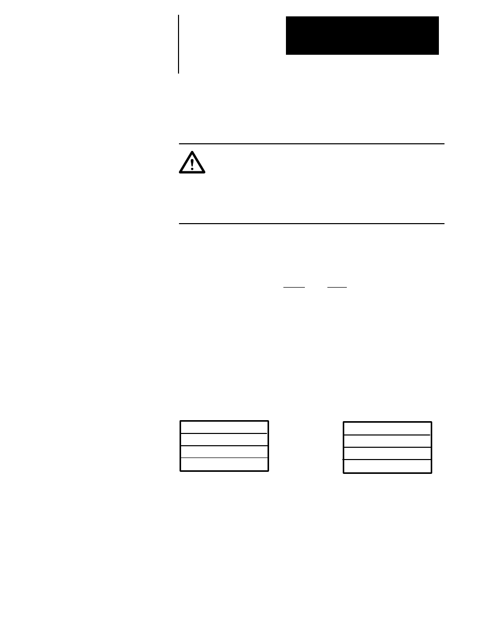
PLC Block Transfer Data –
BTW Instruction Length: 4
BTR Instruction Length: 4
PLC DH+ Data –
Write
Read
Size In Elements:
4
4
Processor Type:
PLC–5
PLC–5
Destination Address:
N15:0–3
N15:0–3
Message Structure –
Message Header Information:
Word 1: 0
Word 2: 0
Function Code, Word 3: 781
Write Message Length, Word 4: 8 bytes
WORD
0
0
781
8
BTW
BTR
0
0
781
See Note
1
2
3
4
NOTE:
Word 4 of the BTR instruction is broken down into
two bytes. The High byte contains the status bits
per table 3–H. The low byte contains the Drive
message length in bytes.
Message Operation – Puts the Drive in the Autotune Mode for
measuring system inertia. Once in this mode the Drive waits for a
“START” input to the Drive before beginning the measure procedure. The
procedure gathers information about motor inertia and connected load
inertia by accelerating and decelerating the motor under conditions
controlled by the Autotune firmware.