Autotune update system inertia – Rockwell Automation 1395 Multi-Comm Hardware/Software User Manual
Page 69
Chapter 3
Configuration & Interfacing
3–58
Refer to the Drive instruction manual (1395–5.xx) for a complete
description of how Auto tuning operates.
This function requires the message header only. The status byte will
indicate the success or ineffectiveness of the request.
Autotune Update System Inertia
This function updates the Drives internal database with the system inertia
(parameter 703) and the maximum achieveable velocity loop bandwidth
(parameter 701) as calculated by the auto tune firmware and provides the
data to the PLC Controller in the BTR message.
PLC Block Transfer Data –
BTW Instruction Length: 4
BTR Instruction Length: 8
PLC DH+ Data –
Write
Read
Size In Elements:
4
8
Processor Type:
PLC–5
PLC–5
Destination Address:
N15:–3
N15:0–7
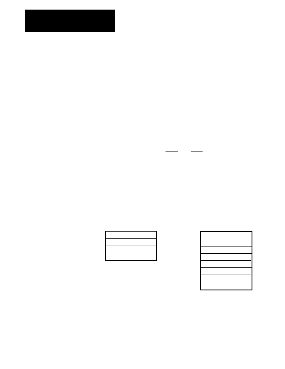
Message Structure –
Message Header Information:
Word 1: 0
Word 2: 0
Function Code, Word 3: 1037
Write Message Length, Word 4: 8 bytes
WORD
0
0
1037
8
BTW
BTR
0
0
1037
See Note
1
2
3
4
NOTE:
Word 4 of the BTR instruction is broken down into
two bytes. The High byte contains the status bits
per Table 3–H. The low byte contains the Drive
message length in bytes.
Parameter 701
Parameter Data
Parameter 703
Parameter Data
Message Operation – The AUTOTUNE UPDATE SYSTEM INERTIA
function updates the Drives internal database with the system inertia
(parameter #701) and maximum achievable bandwidth (Parameter #703) as
calculated by the auto tune firmware, and provides the data to the PLC
Controller in the BTR Message.