Dc input power system (compac / mi-compac family) – Vicor VI-J00 Family DC-DC Converters and Configurable Power Supplies User Manual
Page 54
Design Guide & Applications Manual
For VI-200 and VI-J00 Family DC-DC Converters and Configurable Power Supplies
VI-200 and VI-J00 Family Design Guide
Rev 3.5
vicorpower.com
Page 53 of 98
Apps. Eng. 800 927.9474
800 735.6200
RECOMMENDED INPUT LINE FUSING
The ComPAC must be fused externally. The table below
lists the fuse ratings for one, two and three-up units
(maximum output 200, 400 and 600 W).
RECOMMENDED INPUT WIRING AND TORQUE
RECOMMENDED OUTPUT WIRING
Use the output wire gauge that corresponds to the output
current of the ComPAC unit:
Long cable runs, or wires in large bundles will require
heavier cable to avoid excessive voltage drops or overheating.
GROUNDING
For safe operation, the ComPAC unit must be grounded.
Connect a ground lead to the terminal marked (GND). Use
the same wire gauge as that specified for your ComPAC
unit’s input voltage connections.
MASTER DISABLE
The ComPAC incorporates an optically isolated Master
Disable input which will shut down the ComPAC output
when a current is driven through the disable terminals.
DISABLE CURRENT
• 4 mA DC minimum for 1-up ComPAC
• 8 mA DC minimum for 2-up ComPAC
• 12 mA DC minimum for 3-up ComPAC
TRIMMING
The nominal output voltage of the ComPAC can be
adjusted from 110% to 50% of nominal voltage. Refer to
, Section 5, for external resistor
values. DO NOT trim the outputs higher than 110% of
their nominal output power (output overvoltage protection
may trigger). When the output is trimmed up, do not
exceed its maximum rated output power.
NOTE: 10 V, 12 V, and 15 V outputs, standard trim
range ±10%, 3.3 V output trim range 2.20 to 3.63 V.
REMOTE SENSING
+SENSE and –SENSE must be connected locally or remotely.
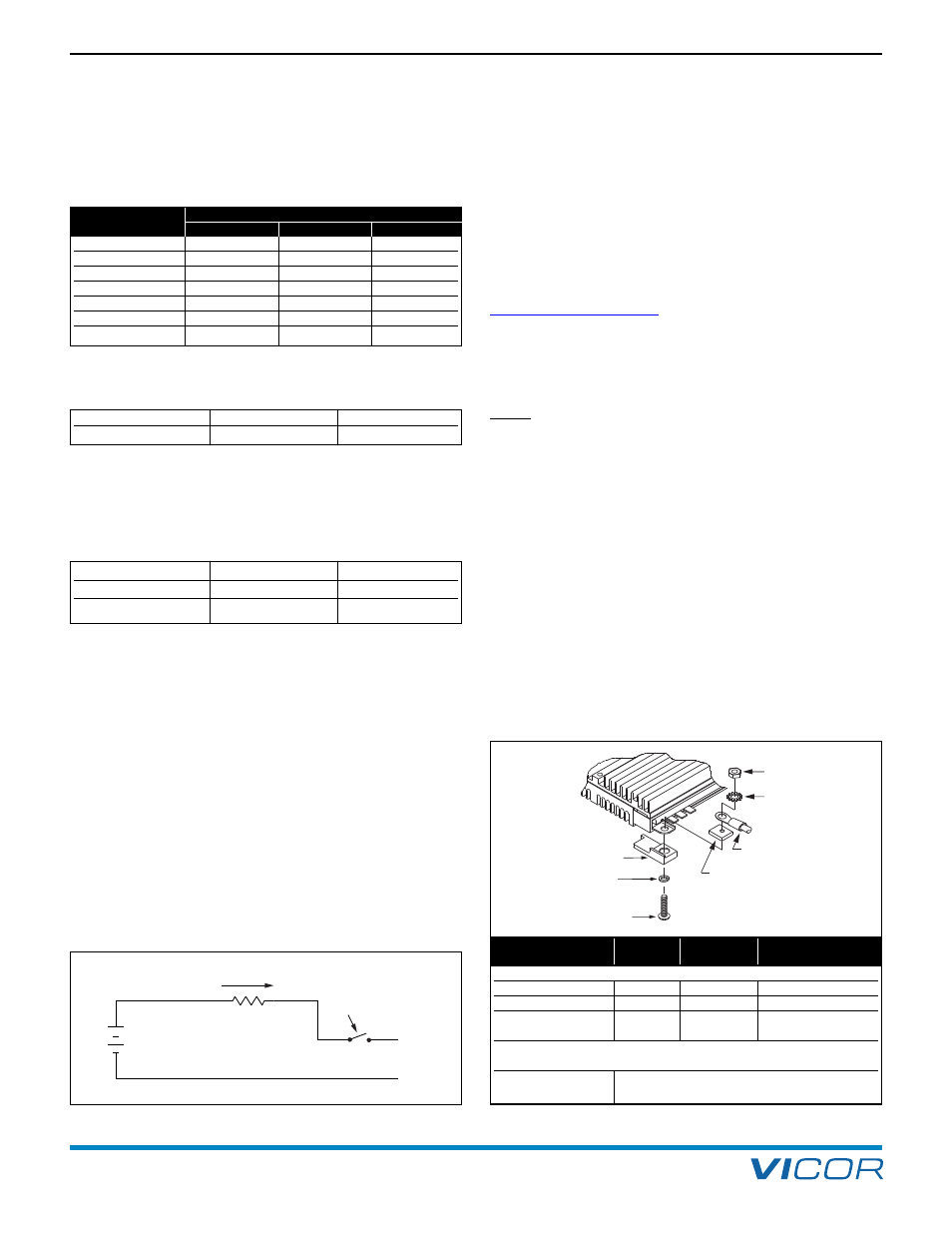
OUTPUT TERMINAL CONNECTIONS
A hardware kit with parts for output terminal connections is
provided with each ComPAC unit. The following drawing
shows the assembly of those parts for the proper
connection of metal power terminals. Assembly for PCB
power terminals is the same except that they do not require
an external tooth lockwasher. See Figure 17–2 for the
recommended torque level for each stud size.
17. DC Input Power System (ComPAC / MI-ComPAC Family)
20 mA Max.
Disable
DIS+
DIS–
+
V
Figure 17–1 — ComPAC module disable
EXTERNAL TOOTH
LOCKWASHER
#10 TERMINAL
RETAINING NUT
#10 NUT PLATE
USER OUTPUT
TERMINALS
#10 BRASS STUD
HELICAL
LOCKWASHER
(FITS WITHIN
OPENING PROVIDED)
TERMINAL COVER
NEGATIVE
Figure 17–2 — Output terminal connections
24 V
10 A / 32 V
20 A / 32 V
30 A / 32 V
24 V (wide)
12 A / 32 V
20 A / 32 V
30 A / 32 V
28 V (military)
10 A / 250 V
20 A / 250 V
30 A / 125 V
48 V
8 A / 60 V
15 A / 60 V
25 A / 60 V
48 V (wide)
6 A / 100 V
15 A / 100 V
25 A / 100 V
270 V (military)
2 A / 250 V
4 A / 250 V
6 A / 250 V
300 V
2 A / 250 V
4 A /250 V
6 A / 250 V
Nominal
Fuse Rating
Input Voltage
1-Up
2-Up
3-Up
1-Up
#16 AWG
10 in-lb
2-Up
#14 AWG
15 in-lb
105 A – 160 A: #4 26 A – 40 A: #10
7 A – 10 A: #16
66 A – 104 A: #6 16 A – 25 A: #12
4 A – 6 A: #18
41 A – 65 A: #8 11 A – 15 A: #14
0 A – 3 A: #20
–OUT, +OUT Terminals
LC, PC, RC Series
PCB
8-32 UNC
10 in-lbs (1.1 N-m)
MC and NC Series
Metal
10-32 UNC
15 in-lbs (1. 7 N-m)
QC Series
PCB
8-32 UNC
10 in-lbs (1.1 N-m)
Metal
10-32 UNC
15 in-lbs (1.7 N-m)
+ / – SENSE, TRIM Terminals
All Models
Sized to accept Amp Faston
©
insulated
receptacle #2-520184-2.
Terminal and
Terminal
Stud
Recommended
Product Model
Style
Size
Torque