Output voltage trimming – Vicor VI-J00 Family DC-DC Converters and Configurable Power Supplies User Manual
Page 10
Design Guide & Applications Manual
For VI-200 and VI-J00 Family DC-DC Converters and Configurable Power Supplies
VI-200 and VI-J00 Family Design Guide
Rev 3.5
vicorpower.com
Page 9 of 98
Apps. Eng. 800 927.9474
800 735.6200
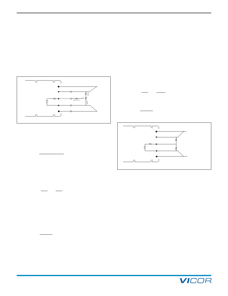
5. Output Voltage Trimming
TRIMMING UP +10%
To trim 10% above the nominal output voltage, the
following calculations are needed to determine the value
of R8. This calculation is dependent on the output voltage
of the module. A 12 V output will be used as an example.
(Figure 5–3)
It is necessary for the voltage at the TRIM pin to be 10%
greater than the 2.5 V reference. This offset will cause the
error amplifier to adjust the output voltage up 10% to 13.2 V.
V
1
= 2.5 V + 10% = 2.75 V
I
R5
=
(2.75 V – 2.5 V)
= 25 µA
10 k
Ω
Since I
R5
= I
R6
,
the voltage drop across R6 = (90 k
Ω) (25 µA) = 2.25 V.
Therefore, V
2
= 2.75 V + 2.25 V = 5 V. The current
through R7 (10 k
Ω pot) is:
I
R7
=
V
2
=
5
= 500 µA
R7 10 k
Using Kirchoff’s current law:
I
R8
= I
R7
+ I
R6
= 525 µA
Thus, knowing the current and voltage, R8 can be
determined:
V
R8
= (V
out
+ 10%) – V
2
= 13.2 V – 5 V = 8.2 V
R8 =
(8.2 V)
= 15.6 k
Ω
525 µA
This resistor configuration allows a 12 V output module
to be trimmed up to 13.2 V and down to 10.8 V. Follow
this procedure to determine resistor values for other
output voltages.
FIXED TRIM
Converters can be trimmed up or down with the addition
of one external resistor, either Ru for programming up or
Rd for programming down. (Figure 5–4)
Example 2. Fixed Trim Up (12 V to 12.6 V).
To determine Ru, the following calculation must be made:
2.5 V + 5% = 2.625 V
V
R5
= V
TRIM
– V
ref
V
R5
= 2.625 – 2.5 = 0.125 V
Knowing this voltage, the current through R5 can be found:
I
R5
=
V
R5
=
0.125
= 12.5 µA
R5 10 k
Ω
V
Ru
= 12.6 V – 2.625 V = 9.975 V
Ru =
9.975
= 798 k
Ω
12.5 µA
Connect Ru from the TRIM pin to the +SENSE. Be sure to
connect the resistor to the +SENSE, not the +OUT, or
drops in the positive output lead as a function of load will
cause apparent load regulation problems.
Example 3. –25% Fixed Trim Down (24 V to 18 V).
The trim down methodology is identical to that used in
Example 2, except that it is utilized to trim the output of a
24 V module down 25% to 18 V. The voltage on the
TRIM pin must be reduced 25% from its nominal setting
of 2.5 V. This is accomplished by adding a resistor from
the TRIM pin to –SENSE.
2.5 V – 25% = 1.875 V
V
R5
= V
bandgap
– V
TRIM
= 2.5 V – 1.875 V = 0.625 V
I
V2
R6 90 k
Ω
TRIM
+ SENSE
– SENSE
– OUT
R5 10 k
Ω
[a]
(internal)
V1
R8
R8
R7 10 k
Ω POT
500
µA
25
µA
2.5 V
[a]
reference
(internal)
+ OUT
[a]
For Vout
<3.3 V, R5 = 3.88 kΩ and internal reference = 0.97 V.
Figure 5–3 — Circuit diagram “Trim Up”
TRIM
+ OUT
+ SENSE
– SENSE
– OUT
Rd
Ru
Trim Resistor for UP
Programming
Trim Resistor for DOWN
Programming
or
2.5 V
[a]
reference
(internal)
R5 10 k
Ω
[a]
(internal)
[a]
For Vout
<3.3 V, R5 = 3.88 kΩ and internal reference = 0.97 V.
Figure 5–4 — Fixed trimming