Offline front end – Vicor VI-J00 Family DC-DC Converters and Configurable Power Supplies User Manual
Page 50
Design Guide & Applications Manual
For VI-200 and VI-J00 Family DC-DC Converters and Configurable Power Supplies
VI-200 and VI-J00 Family Design Guide
Rev 3.5
vicorpower.com
Page 49 of 98
Apps. Eng. 800 927.9474
800 735.6200
THERMAL CONSIDERATIONS
Free Convection Derating.
• 250 W: Derate output power linearly at 7.2 W/°C
over 50°C.
• 500 W: Derate output power linearly at 14.3 W/°C
over 50°C.
• 750 W: Derate output power linearly at 18.8 W/°C
over 45°C.
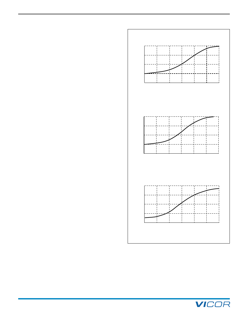
Forced Convection. The curves to the right represent
worst case data for chassis mounted (enclosed) front
ends; i.e., low line, full load. System conditions such as
higher line voltage, lighter load or PC mount versions of
the front ends will increase reliability if the following data
is used as the nominal design criteria.
The sigmoid shape of the curves at low airflow is due to
the chassis mount cover restricting the airflow to the
inboard components. When an airflow of approximately
200 LFM is achieved, the velocity of air rushing over the
cover causes air to be pulled in through the side
perforations, resulting in a rapid improvement in the
cooling of internal components.
250 W
500 W
750 W
40
80
70
60
50
500
400
300
200
100
0
Airflow (LFM)
Am
bi
en
t T
em
pe
ra
tu
re
°
C
600
40
80
70
60
50
500
400
300
200
100
0
Airflow (LFM)
Am
bi
en
t T
em
pe
ra
tu
re
°
C
600
40
80
70
60
50
600
500
400
300
200
100
0
Airflow (LFM)
Am
bi
en
t T
em
pe
ra
tu
re
°
C
Figure 16–2 — Maximum ambient temperature vs. airflow (LFM)
over cover (full load, 90 Vac Input, chassis mount)
16. Offline Front End