Output voltage trimming – Vicor VI-J00 Family DC-DC Converters and Configurable Power Supplies User Manual
Page 11
Design Guide & Applications Manual
For VI-200 and VI-J00 Family DC-DC Converters and Configurable Power Supplies
VI-200 and VI-J00 Family Design Guide
Rev 3.5
vicorpower.com
Page 10 of 98
Apps. Eng. 800 927.9474
800 735.6200
Knowing this voltage, the current through R5 can be found:
I
R5
=
V
R5
=
0.625
= 62.5 µA
R5 10 k
Ω
The voltage across the resistor, Rd, and the current
flowing through it are known:
Rd =
(2.5 V – 0.625 V)
= 30 k
Ω
62.5 µA
Connect Rd (Figure 5– 4) from the TRIM pin to the –SENSE
of the module. Be sure to connect the resistor to the
–SENSE, not the –OUT, or drops in the negative output
lead as a function of load will cause apparent load
regulation problems.
DYNAMIC ADJUSTMENT PROCEDURE
Output voltage can also be dynamically programmed by
driving the TRIM pin from a voltage or current source;
programmable power supplies and power amplifier
applications can be addressed in this way. For dynamic
programming, drive the TRIM pin from a source referenced
to the negative sense lead, and keep the drive voltage in
the range of 1.25 – 2.75 V. Applying 1.25 – 2.5 V on the
TRIM pin corresponds to 50 – 100% of nominal output
voltage. For example, an application requires a +10, 0%
(nominal), and a –15% output voltage adjustment for a 48 V
output converter. Referring to the table below, the voltage
that should be applied to the trim pin would be as follows:
V
TRIM
V
OUT
Change from nominal
2.125
40.8
–15%
2.5
48
0
2.75
52.8
+10%
The actual voltage range is further restricted by the
allowable trim range of the converter. Voltages in excess
of 2.75 V (+10% over nominal) may cause overvoltage
protection to be activated. For applications where the
module will be programmed on a continuous basis the
slew rate should be limited to 30 Hz sinusoidal.
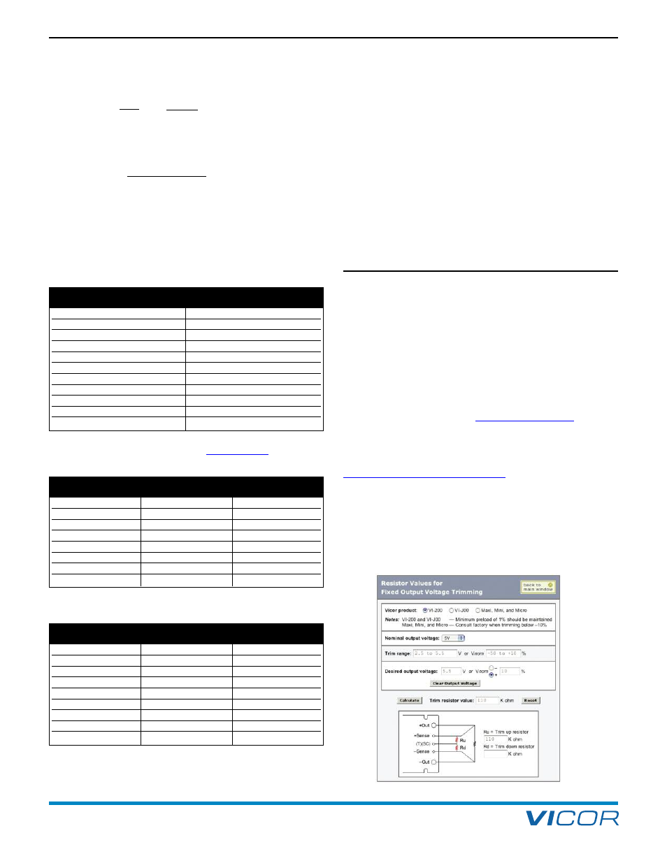
TRIMMING ON THE WEB
Trim values are calculated automatically. Design
Calculators are available on Vicor’s website in the
PowerBench
TM
section at
Resistor values can be easily determined for fixed trim up,
fixed trim down and for variable trimming applications.
In addition to trimming information, the website also
includes design tips, applications circuits, EMC
suggestions, thermal design guidelines and PDF data
sheets for all available Vicor products.
Percent
Resistance
–5 %
190 k
Ω
–10 %
90 k
Ω
–15 %
56.7 k
Ω
–20 %
40 k
Ω
–25 %
30 k
Ω
–30 %
23.3 k
Ω
–35 %
18.6 k
Ω
– 40 %
15 k
Ω
– 45 %
12.2 k
Ω
–50 %
10 k
Ω
Vnom
V (Desired)
Trim Resistor
[a]
5 V
4.5 V
90.9 k
Ω
3.3 V
19.6 k
Ω
2.5 V
10.0 k
Ω
15 V
13.8 V
115 k
Ω
24 V
20 V
49.9 k
Ω
48 V
40 V
49.9 k
Ω
36 V
30.1 k
Ω
Vnom
V (Desired)
Trim Resistor
[a]
5 V
5.2 V
261 k
Ω
5.5 V
110 k
Ω
12 V
12.5 V
953 k
Ω
13.2 V
422 k
Ω
15 V
15.5 V
1.62 M
Ω
16.5 V
562 k
Ω
24 V
25 V
2.24 M
Ω
48 V
50 V
4.74 M
Ω
Table 5–1 — Values for trim down by percentage (Refer to product
data sheet for allowable trim ranges at
Values for Trim Down by Percentage
Fixed Trim Down
Table 5–2a — Values for fixed trim down by voltage
Fixed Trim Up
Table 5–2b — Values for fixed trim up by voltage
[a]
Values listed in the tables are the closest standard 1% resistor values.
5. Output Voltage Trimming