Offline front end – Vicor VI-J00 Family DC-DC Converters and Configurable Power Supplies User Manual
Page 51
Design Guide & Applications Manual
For VI-200 and VI-J00 Family DC-DC Converters and Configurable Power Supplies
VI-200 and VI-J00 Family Design Guide
Rev 3.5
vicorpower.com
Page 50 of 98
Apps. Eng. 800 927.9474
800 735.6200
3-PHASE FRONT ENDS
Vicor’s 3-phase front-ends are available as chassis mount
products that deliver reliable DC bus voltage to VI-x6x
Family (nominal 300 Vdc input) converters up to 1.5 kW,
3 kW and 5 kW.
Front ends operate from 3-phase (4-wire delta or 4 or
5-wire wye) AC mains input and provide conducted EMC
filtering to VDE/FCC Class A, transient surge protection,
inrush current limiting and ENABLE output suitable for
controlling an array of Vicor converters via the GATE IN
pin. Isolated AC-OK and BUS-OK outputs are also provided
for advance warning of DC bus dropout due to AC line
failure and indication of internal DC bus integrity in the
user system, respectively.
These front ends have been designed to comply with
the requirements of major safety agencies when used in
conjunction with the recommended mains switching and
input fusing.
+V
<70 V
AC
MAINS
Vdc–
Vdc+
MOD ENBL
AC-OK –
AC-OK +
BUS-OK +
BUS-OK –
L3
L2
L1
N
GND
+IN
GATE IN
–IN
VI-x6x
Module
+IN
GATE IN
–IN
VI-x6x
Module
F2
F3
F4
Fn
Vce sat.<0.4 V
@ 1.5 mA
+V
<70 V
EARTH
GROUND
+IN
GATE IN
–IN
VI-x6x
Module
+IN
GATE IN
–IN
VI-x6x
Module
+V
<70 V
Vdc–
Vdc+
AC-OK –
AC-OK +
BUS-OK +
BUS-OK –
L3
L2
L1
N
GND
F2
F3
F4
Fn
Vce sat.<0.4V
@ 1.5 mA
+V
<70 V
MOD ENBL
AC
MAINS
EARTH
GROUND
+IN
GATE IN
–IN
VI-x6x
Module
+IN
GATE IN
–IN
VI-x6x
Module
+IN
GATE IN
–IN
VI-x6x
Module
+IN
GATE IN
–IN
VI-x6x
Module
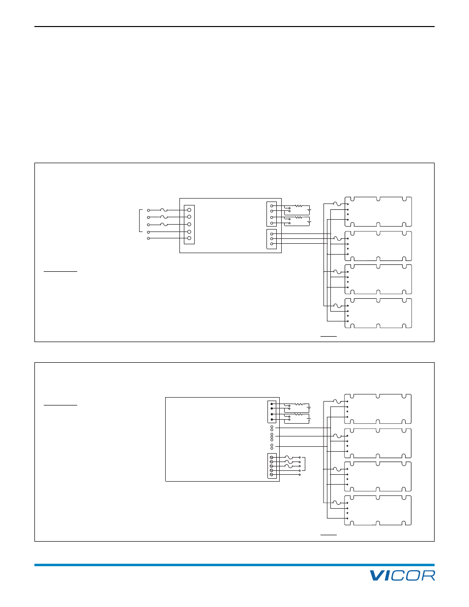
CAUTION: External capacitors connected to +Vdc and –Vdc will
significantly increase inrush current. Also these capacitors are
subject to AC ripple voltages of approximately 40 V at full load.
CAUTION: External capacitors
connected to +Vdc and –Vdc
will significantly increase inrush
current. Also these capacitors are
subject to AC ripple voltages of
approximately 40 V at full load.
Ground all baseplates to Earth Ground
[a]
16. Offline Front End
Figure 16 –3 — 1.5, 3.0 kW Front-end
Figure 16–4 — 5.0 kW Front-end
Ground All Baseplates to Earth Ground
[a]
[a] To control EMC most effectively, the return path to
ground from either the front-end or modules should be made
via a good RF ground (i.e., a braided wire) if possible.
[a] To control EMC most effectively, the return path to
ground from either the front-end or modules should be made
via a good RF ground (i.e., a braided wire) if possible.
NOTE:
x,y capacitors not shown for clarity
NOTE:
x,y capacitors not shown for clarity