Ac input module (aim / mi-aim) – Vicor VI-J00 Family DC-DC Converters and Configurable Power Supplies User Manual
Page 35
Design Guide & Applications Manual
For VI-200 and VI-J00 Family DC-DC Converters and Configurable Power Supplies
VI-200 and VI-J00 Family Design Guide
Rev 3.5
vicorpower.com
Page 34 of 98
Apps. Eng. 800 927.9474
800 735.6200
SELECTING CAPACITORS FOR AIM MODULES
Hold-up Time. For maximum flexibility, an external
capacitor (Figure 12–2, C1) is used to set the system’s
hold-up requirements. Hold-up time, for purposes of this
application note, is defined as the time interval from loss
of AC power to the time a DC-DC converter begins to
drop out of regulation (Figure 12–3, T4 to T5). Hold-up
time is a function of line voltage, hold-up capacitance,
output load, and that point on the AC waveform where
the line drops out. For example, if the AC line fails just
after the hold-up capacitors were recharged, hold-up time
will be much greater (Figure 12–3, T3 to T5) than if the
AC line fails just prior to another recharge (Figure 12–3,
T4 to T5).
The basic equations involved in calculating hold-up time are:
1 X C1 X V
p2
– 1 X C1 X V
do2
= P
IM
X (T5 – T3)
(1)
2
2
solving for C1:
C1 = 2 X
P
IM
x (T5 – T3)
(2)
V
p2
– V
do2
Where P
IM
is power delivered from the AIM:
P
IM
= Module Output Power =
P
OM
(3)
Module Efficiency
Eff. % / 100
The energy (Joules) delivered from the AIM from the time
power is lost (T4), until loss of an output (Figure 12–2, T5):
Energy (Joules) = P
IM
x (T5 - T4) (Watt – Seconds)
(4)
where: P
OM
= Output power from all the modules
P
IM
= Input power to the modules
(output power from the AIM)
Eff = Weighted average efficiency of all modules
The input power to the converter(s) during normal operation
is supplied from the AC line during the conduction time
of the rectifiers (T2 to T3) internal to the AIM and by the
energy stored in C1 when the rectifiers in the AIM are
reverse biased (T1 to T2). In the event of an AC failure
(T4), C1 must continue to provide energy to the converters
until either AC returns or the converter drops out (T5).
The energy stored in C1 at the peak of the AC is:
1
x C1 x V
p2
= Joules
(5)
2
The energy stored in C1 when the converter drops out of
regulation is:
1
x C1 x V
do2
= Joules
(6)
2
The energy delivered by C1 to the converters during
normal operation is:
P
IM
x (T2 – T1) = Joules
(7)
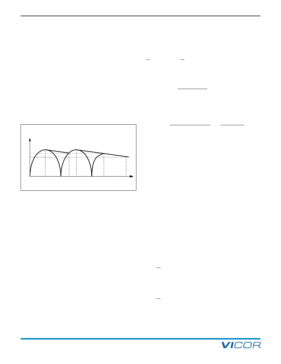
RECTIFIED
AC
T0
T1
T2
T3
T4
Vp
Vv
Vdo
TIME
T5
Figure 12–3 — AC waveforms
12. AC Input Module (AIM / MI-AIM)