Vicor VI Chip High Voltage BCM Customer Evaluation Board User Manual
Vicor Hardware
UG:010
vicorpower.com
Applications Engineering: 800 927.9474
Page 1
Features
• Oscilloscope probe jack for output voltage
and ripple measurements
• Simple to use
• Ring lug or solder connections
Introduction
WARNING: The High Voltage BCM
®
Customer Evaluation Board contains exposed
metal carrying lethal voltages when under power. Care should be taken to protect the
user from accidental contact when under power.
The BCM
®
Evaluation Board offers a convenient means to evaluate the performance of
Vicor’s BCM bus converter and has been optimized for user convenience. Refer to the appropriate
data sheet for performance and operating limits. Data sheets are available
at
It is important to remember the fast response of most BCM modules can readily show the
limitations of the source, load, and associated wiring connected to the evaluation board.
Care should be exercised to minimize stray source and load impedances in order to fully
exercise the module.
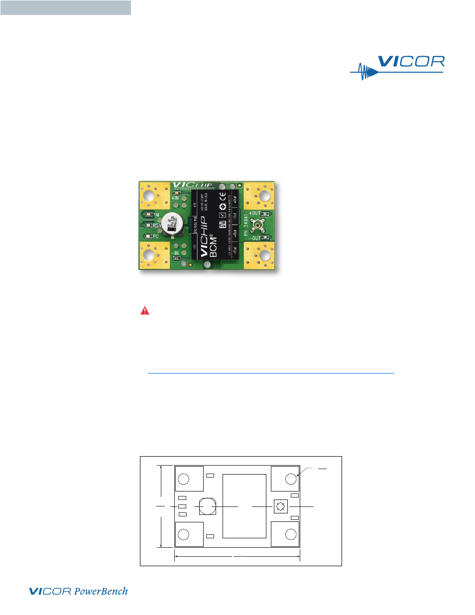
Please refer to Figure 1 for locations of the input and output connections as viewed from the
component side. Wires may be soldered directly to the pads instead of ring lugs if desired to
minimize circuit impedances.
VI Chip
®
High Voltage BCM
®
Customer Evaluation Board
Contents
Page
TM
RSV
PC
+IN
–IN
CL
2.52
64,0
Ø 0.20 Typ
5.08
1.65
41.9
+OUT
– OUT
C1
BCM
TM
Bus Converter
J1
TP1
TP2
TP7
TP4
TP6
TP5
Figure 1
BCM
TM
Customer Evaluation Board
layout and dimensional drawing,
component side.
USER GUIDE | UG:010