Input attenuator module (iam / mi-iam) – Vicor VI-J00 Family DC-DC Converters and Configurable Power Supplies User Manual
Page 46
Design Guide & Applications Manual
For VI-200 and VI-J00 Family DC-DC Converters and Configurable Power Supplies
VI-200 and VI-J00 Family Design Guide
Rev 3.5
vicorpower.com
Page 45 of 98
Apps. Eng. 800 927.9474
800 735.6200
OUTPUT OVERCURRENT / SHORT CIRCUIT PROTECTION
Output overcurrent protection is a foldback type, followed
by a timed latched shut down should the overcurrent
persist beyond 2 ms. If the overcurrent condition is
removed before the timeout interval, auto restart shall
occur. Should latched shut down occur, input power must
be recycled to restart.
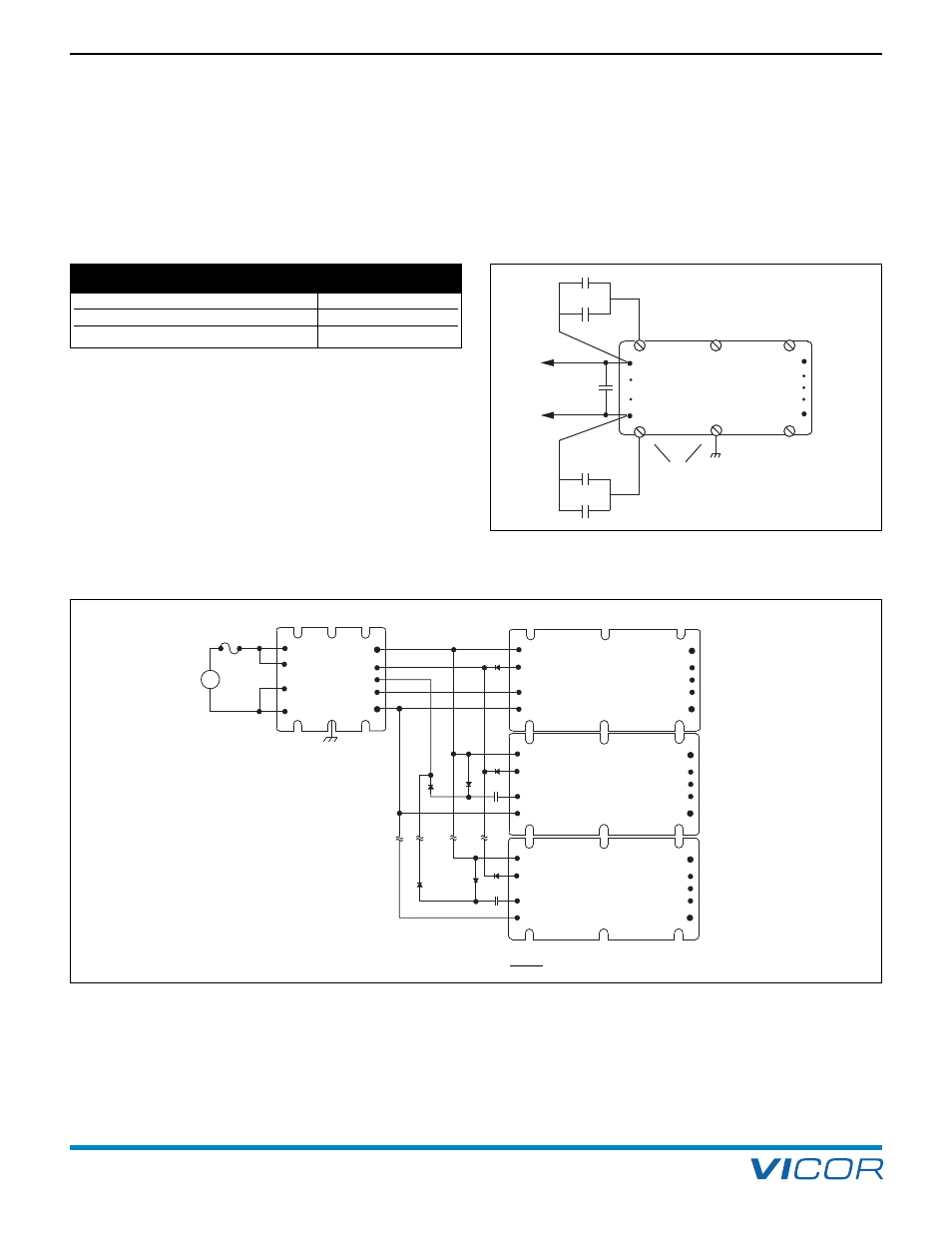
EXPANSION CAPABILITIES
The Input Attenuator Module incorporates a PARALLEL pin
permitting power expansion as long as the total output
power from the DC-DC converters does not exceed the
power rating of each Input Attenuator Module (EMC
specifications are guaranteed for up to two input
attenuators in parallel). It is necessary to include a 100
Ω,
1/4 W resistor between the negative outputs of
the Input Attenuator Modules to ensure equal potential at
these points when paralleling Input Attenuator Modules,
so as not to impact the effectiveness of the internal
common-mode choke.
Driver/
Booster
C1
+IN
–IN
GATE
OUT
GATE
IN
Connection to module baseplate
or ground plane
connected to baseplate
4,700 pF
4,700 pF
+OUT
–OUT
–S
+S
TRIM
To IAM
D1
D2
D2
C2
C2
IAM
GATE OUT
PAR
GATE IN
+OUT
–OUT
–IN
–IN
+IN
+IN
D1, D2, D3: 1N4148
[a]
C2: 470 pF/500V
D1
–Out
–S
Trim
+S
+OUT
+IN
GATE
IN
GATE
OUT
–IN
Driver
+
–
[a]
For bus voltages greater than 75 V,
a 1N4006 diode should be used for
the diodes (D3) connected to the
GATE IN pins.
–OUT
–S
TRIM
+S
+OUT
+IN
GATE
IN
GATE
OUT
–IN
Driver
–OUT
–S
TRIM
+S
+OUT
+IN
GATE
IN
GATE
OUT
–IN
Driver
D3
D3
D3
Figure 14–3 — External x,y capacitors for EMC requirements
Table 14–5 — IAM overcurrent
Figure 14–4 — IAM multiple Driver interconnection
14. Input Attenuator Module (IAM / MI-IAM)
24 Vin “W”, 28 Vin, 48 Vin “N”
20 A
24 Vin, 48 Vin
15 A
270 Vin, 300 Vin
4 A
Output Overcurrent Threshold
NOTE:
x,y capacitors not shown for clarity