8 boom installation, Boom installation – SkyTrak 6036 Service Manual User Manual
Page 56
Boom
3-14
6036, 6042, 8042, 10042, 10054
18. Insert the shoulder bolt from the top down and
secure in place with a locknut.
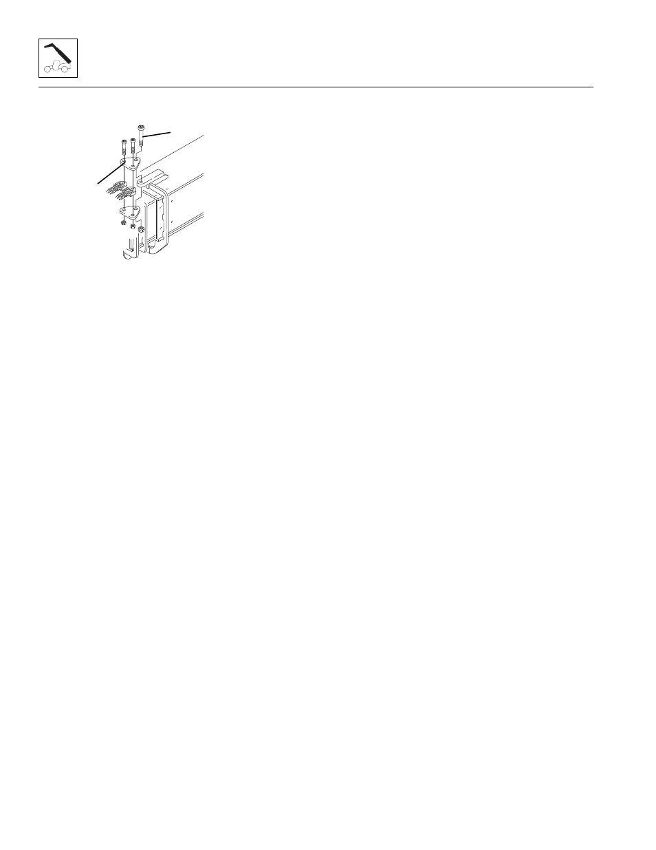
19. Assemble the two extend chains to the mount if the
yoke plates (14) were removed from the extend
chains. Secure in place with a locknut. Tighten the
locknut securely; but the yoke plates must pivot
freely.
20. Align the holes in the yoke plates with the hole in the
mount on the first boom section. Coat the shoulder
bolt (15) with anti-seize compound and insert the
shoulder bolt through the yoke plates and the mount
on the boom. Secure in place with a locknut. Tighten
the locknut securely; but the yoke plates must pivot
freely.
21. Install the quick attach and Attachment Tilt cylinder
to the front of the boom. Refer to Section 3.8.2,
“Quick Attach Installation.”
22. If necessary, install the Auxiliary hydraulic fittings to
the front of the boom.
23. Uncap and connect the previously labeled hoses to
the Attachment Tilt cylinder.
24. Properly connect the battery.
25. Remove the Do Not Operate Tags from both the
ignition key switch and the steering wheel.
26. Start the engine and operate all boom functions
several times. Check the chain tension again and
adjust as necessary. Check for leaks, and check the
hydraulic fluid level in the tank; add fluid if required.
27. Clean up all debris, hydraulic fluid, etc., in, on, near
and around the machine.
28. Install the rear cover to the boom.
29. Close and secure the rear door.
3.4.8
Boom Installation
1. Park the machine on a hard, level surface, level the
machine, fully retract the boom, lower the boom,
place the transmission control lever in
(N) NEUTRAL, engage the park brake and shut the
engine OFF.
2. Using suitable slings, balance the boom assembly,
lift and guide the boom assembly into place. Align
the frame pivot bores with the boom assembly pivot
bores. Install the boom pivot pin.
3. Move the Attachment Tilt joystick in both directions
to relieve any trapped pressure in the Attachment Tilt
system. If the machine is equipped with Auxiliary
controls, move the Auxiliary hydraulic joystick in both
directions to relieve any trapped pressure in the
Auxiliary hydraulic system.
4. With the sling still in place, install the rod end of the
compensation cylinder, pin and bolt. Apply Loctite
®
242
TM
torque lock bolt to 100-110 lb-ft (135-149 Nm).
5. With the sling still in place, install the rod end of each
lift/lower cylinder, pin and bolt. Apply Loctite
®
242
TM
torque lock bolt to 200-215 lb-ft (271-291 Nm).
6. Uncap and connect the hydraulic hoses at the rear
of the boom.
7. Connect the boom proximity sensor at the rear of the
boom.
8. Recheck wear pad gaps to ensure they meet the
minimum gap requirement. Shim as necessary.
9. Ensure that the boom chains are properly adjusted.
Refer to Section 3.7.6, “Boom Chain Tension
Adjustment (6036, 6042, 8042 & 10042).”
10. Properly connect the battery.
11. Remove the Do Not Operate Tags from both the
ignition key switch and the steering wheel.
12. Start the engine and operate all boom functions
several times. Check for leaks, and check the
hydraulic fluid at the reservoir; add fluid if required.
SH1871
14
15