4 relay testing, 5 outrigger pressure switches (10054 only), Relay testing – SkyTrak 6036 Service Manual User Manual
Page 236: Outrigger pressure switches (10054 only)
Stabil-TRAK™
System and Boom Interlock System
10-8
6036, 6042, 8042, 10042, 10054
10.4.4
Relay Testing
If after checking the electrical system, a relay is suspect,
test the relay as follows:
1. Park the machine on a firm, level surface, level the
machine, fully retract the boom, lower the boom,
place the travel select lever in the (N) NEUTRAL
position, engage the parking brake, straighten all
wheels and shut the engine OFF.
2. Place a Do Not Operate Tag on both the ignition key
switch and steering wheel, stating that the machine
should not be operated.
3. Open the rear door. Allow the system fluids to cool.
4. Properly disconnect the battery.
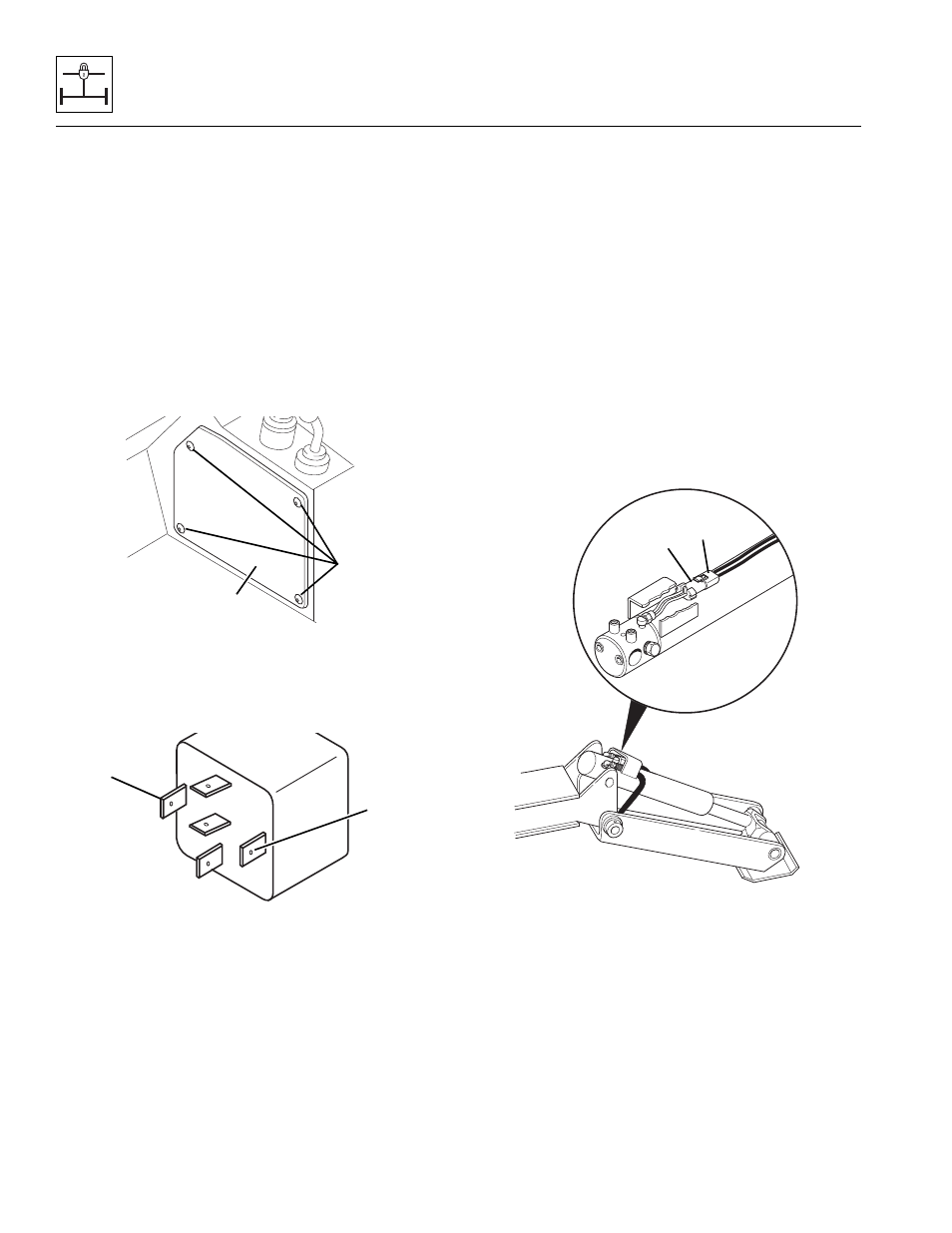
5. Fuse block relays (3 through 10) are located in fuse
block and is mounted behind right side console
access panel (14). To gain access, remove
screws (15) that secure right side panel in place.
6. Remove suspect relay from fuse panel.
7. Apply proper voltage to relay coil at terminal 86 (16)
and attach the ground (-) probe to terminal 85 (17),
ground. An audible click should be heard indicating
that relay is functioning properly.
8. When reassembling right side console access panel
(14), torque screws (15) to 3–5 lb-ft (13–22 Nm).
9. Properly connect the battery.
10. Close and secure rear engine compartment door.
11. Remove the Do Not Operate Tags from both the
ignition key switch and the steering wheel.
10.4.5
Outrigger Pressure Switches
(10054 Only)
a. Testing
If after checking the electrical system, a pressure switch
is suspect, test the switch as follows:
1. Park the machine on a firm, level surface, level the
machine, fully retract the boom, lower the boom,
place the travel select lever in the (N) NEUTRAL
position, engage the parking brake, straighten all
wheels and shut the engine OFF.
2. Lower the outriggers onto firm terrain, and shut the
engine OFF.
3. Place a Do Not Operate Tag on both the ignition key
switch and steering wheel, stating that the machine
should not be operated.
4. Disconnect the pressure switch wiring connector
(18) from the harness connector (19).
5. Check for continuity across the red and black wires at
the pressure switch wiring connector (18). If there is
no continuity across the red and black wires, replace
the switch.
6. Remove Do Not Operate Tags from both ignition key
switch and steering wheel when done.
OH2431
15
14
86
85
30
87
87A
MN1820
16
17
MH4121
18
19