8 unloader valve (6036 & 6042 only), Unloader valve (6036 & 6042 only) – SkyTrak 6036 Service Manual User Manual
Page 180
Hydraulic System
8-28
6036, 6042, 8042, 10042, 10054
b. Steer Select Manifold and Valve Disassembly,
Cleaning, Inspection and Assembly
1. Place the steer select assembly on a suitable
work surface.
2. Separate the steer select valve from the manifold by
removing the four socket head capscrews. Discard
the four o-rings.
3. Remove the solenoid valves and cartridges from the
steer select housing.
4. Clean all the components with a suitable cleaner
before inspection.
5. Inspect the solenoid cartridges for proper operation.
Check by shifting the spool to ensure that it is
functioning properly. Check that the spring is intact.
Inspect the cartridge interior for contamination.
6. Inspect internal passageways of the steer select
manifold and valve for wear, damage, etc. If inner
surfaces of the manifold DO NOT display an ultra-
smooth, polished finish, or components are
damaged in any way, replace the manifold or
appropriate part. Often, dirty hydraulic fluid causes
failure of internal seals and damage to the polished
surfaces within the secondary function manifold.
Note: ALWAYS replace seals, o-rings, gaskets, etc.,
with new parts to help ensure proper sealing and
operation. Lubricate seals and o-rings with clean
hydraulic oil.
7. Install the solenoid valves and cartridges in the steer
select housing.
8. Attach steer select valve to the manifold using four
new, oiled o-rings and four socket head capscrews.
c. Steer Select Valve and Manifold Installation
1. Install the steer select valve to the mounting plate on
the frame using two capscrews.
2. Connect all the previously labeled hydraulic hoses,
fittings, solenoid wire terminal leads, etc., to the
steer select valve.
3. Check the routing of all hoses, wiring and tubing for
sharp bends or interference with any rotating
members, and install tie wraps and/or protective
conduit as required. Tighten all hose clamps.
4. Properly connect the battery.
5. Remove the Do Not Operate Tags from both the
ignition key switch and the steering wheel.
6. Start the engine and run at approximately 1/3-1/2
throttle for about one minute without moving the
machine or operating any hydraulic functions.
7. Inspect for leaks and check the level of the hydraulic
fluid in the reservoir. Shut the engine OFF.
Note: Check for leaks and repair as required before
continuing. Add hydraulic fluid to the reservoir as
needed.
8. Wipe up any hydraulic fluid spillage in, on, near and
around the machine, work area and tools.
9. Install the transmission covers.
10. Close and secure the rear door.
d. Steering Test
Refer to Section 8.4.1, “Hydraulic Pressures.”
1. Conduct a pressure check of the steering
hydraulic circuit.
2. Check each steering mode for proper function.
8.7.8
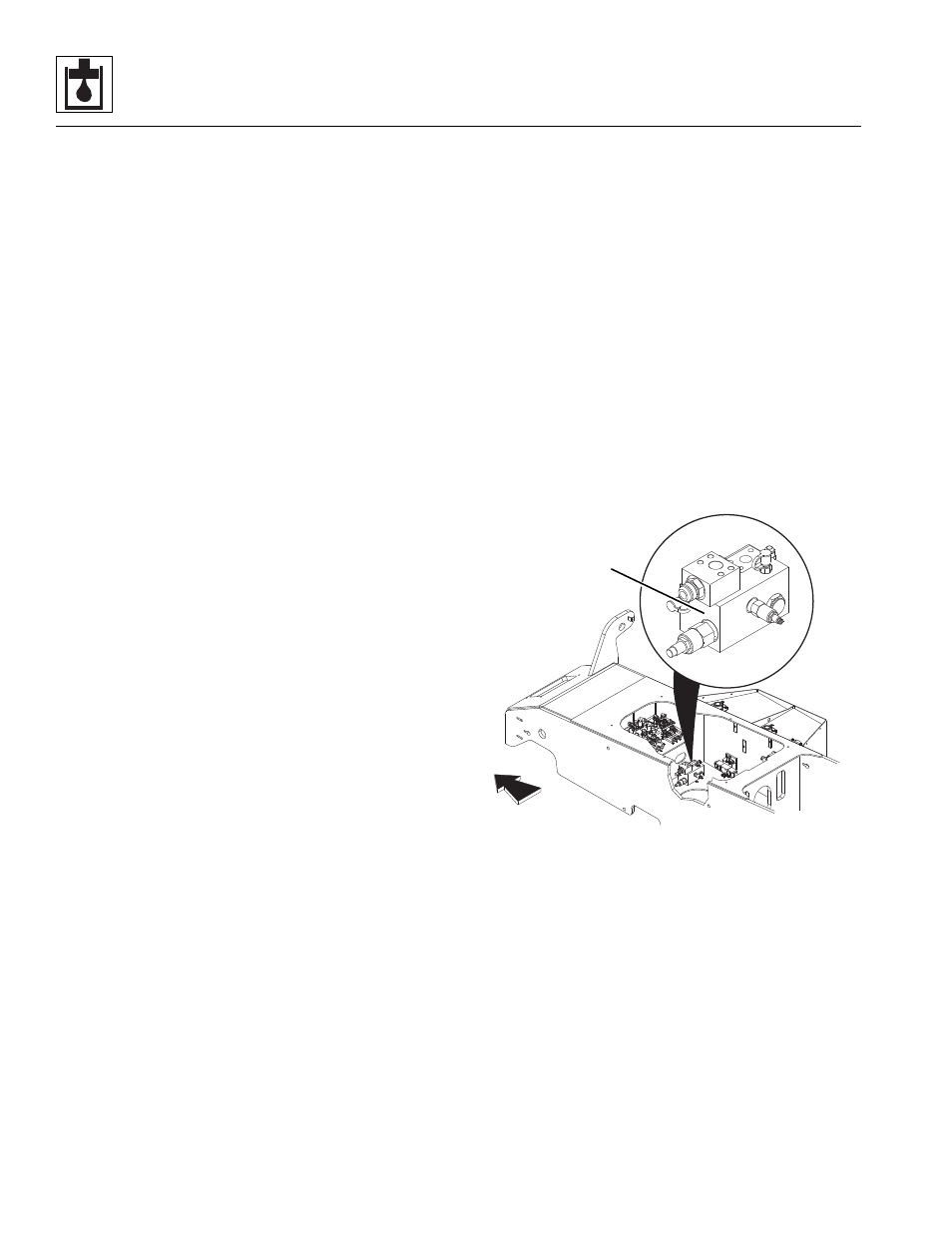
Unloader Valve (6036 & 6042 only)
The unloader valve (1) creates system pressure and
distributes the hydraulic fluid for various machine
functions via its load sense, by to tank (via the oil cooler),
and primary and secondary valve ports. The unloader
valve is secured to the frame toward the front of the
machine near the main control valve.
a. Unloader Valve Removal
1. Park the machine on a firm, level surface, level the
machine, fully retract the boom, raise the boom, place
the transmission control lever in (N) NEUTRAL,
engage the park brake and shut the engine OFF.
2. Place a Do Not Operate Tag on both the ignition key
switch and the steering wheel, stating that the
machine should not be operated.
MA8391
1