10 isolation coupler, 1 isolation coupler removal, 2 isolation coupler installation – SkyTrak 6036 Service Manual User Manual
Page 150: Isolation coupler, Isolation coupler removal, Isolation coupler installation
Engine
7-14
6036, 6042, 8042, 10042, 10054
20. Check for leaks from the engine, main hydraulic
pump and lines, transmission, hydraulic reservoir
and fuel tank. Check the levels of all fluids and
lubricants. Fill as required.
Note: During the full throttle check:
• DO NOT operate any hydraulic function.
• DO NOT steer or apply any pressure to the steering
wheel.
• Keep the transmission in (N) NEUTRAL.
21. Obtain and connect an appropriate engine analyzer
or tachometer. Check the engine rpm at full throttle.
22. Purge the hydraulic system of air by operating all
boom functions through their entire range of motion
several times. Check the hydraulic oil level.
23. Check for proper operation of all components.
24. Turn the engine OFF.
25. Install the side and rear engine covers.
7.10
ISOLATION COUPLER
7.10.1
Isolation Coupler Removal
1. Park the machine on a firm, level surface, level the
machine, fully retract the boom, lower the boom,
place the transmission in (N) NEUTRAL, engage the
parking brake, and shut the engine OFF.
2. Place a Do Not Operate Tag on both the ignition key
switch and steering wheel, stating that the machine
should not be operated.
3. Open the rear door. Allow the system fluids to cool.
4. Properly disconnect the battery.
Note: Rotating the fan belt by hand gives greater
access to removing the drive shaft mounting capscrews.
5. Remove the capscrews and straps that secure the
drive shaft to the transmission yoke.
6. Remove the capscrews and lockwashers securing
the drive shaft to the coupling flange.
Note: It may be necessary to loosen/remove the motor
mounts on either side of the engine to gain access to the
bottom capscrews on the outer half of the coupler. Place
a jack under the bell housing (use a wood block to
support the engine) and carefully lift the engine until the
bottom edge of the bell housing is at the top edge of the
frame member that mounts the rear axle to the frame.
Watch the fan-to-radiator clearance as your are lifting the
engine. If necessary, turn the fan slightly by hand to gain
additional clearance.
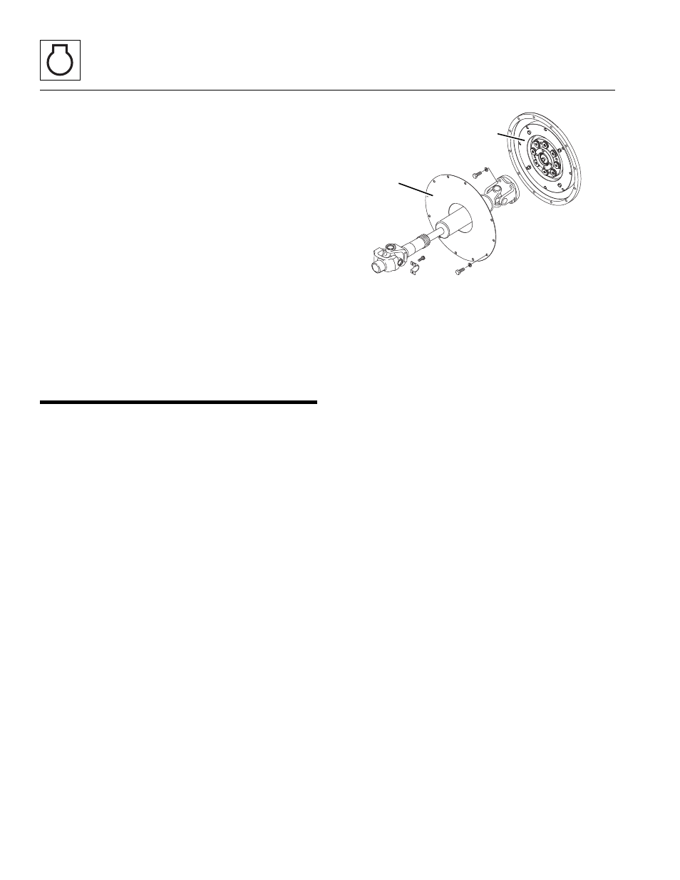
7. Remove the capscrews and lockwashers securing
the access cover plate (3).
8. Remove the capscrews securing the coupler (4) to
the flywheel.
Note: The coupler is heavy and requires two people,
one on each side, to remove.
9. Remove the coupler assembly.
10. At this time, use a suitable cleaner/solvent and
thoroughly clean the mounting lip of the flywheel.
Wipe any debris from the inside of the bell housing.
Use the cleaner to clean the threaded holes around
the flange of the bell housing.
7.10.2
Isolation Coupler Installation
1. Use cleaner to clean the backside of the coupler,
where it comes in contact with the flywheel.
Note: Apply Loctite
®
242
TM
threadlock compound to all of
the capscrews used during assembly.
Note: The new coupler is heavy and requires two
people, one on each side, to install.
2. Place the new coupler into the indentation of the
flywheel and use new hardware to secure the
coupler to the flywheel. DO NOT fully tighten until all
capscrews are in place.
3. After all capscrews are in place, check to be sure the
coupler is resting squarely in the indentation of the
flywheel. Torque all the capscrews to 37 lb-ft (48
Nm).
Note: Before assembling the drive shaft to the coupling;
be sure the access cover plate is placed on the engine-
side of the frame member that mounts the rear axle to
the frame.
MH6360
3
4