SkyTrak 6036 Service Manual User Manual
Page 103
4-9
6036, 6042, 8042, 10042, 10054
Cab and Covers
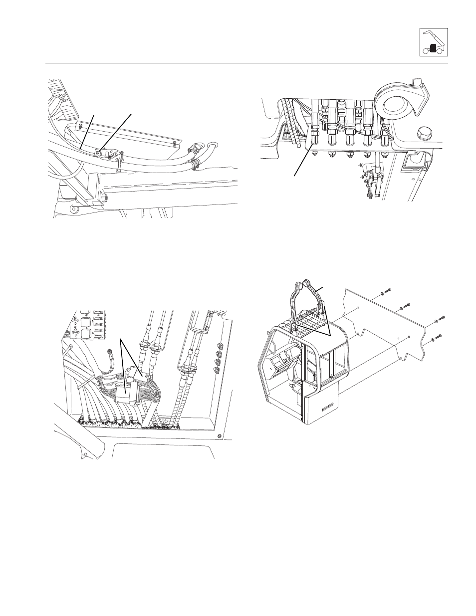
9. Working under the cab, loosen the clamp screw (1)
and disconnect the heater control cable (2) from the
heater control valve. Label, disconnect and cap the
heater hoses.
10. Remove the heater access panel. Label, disconnect
and cap the heater hoses and route them through
the opening in the bottom of the cab.
11. Remove the console panel in the cab.
12. Label and disconnect the two cab-to-wiring harness
connectors (3). Push the connectors through the
opening at the bottom of the cab.
13. Remove the joystick assemblies from the cab. Refer
to Section 4.3.4, a. “Joystick Assembly Removal.”
14. Route the joystick cables through the opening at the
bottom of the cab.
15. Working under the cab, label, disconnect and cap
the hydraulic hoses at the cab fittings (4). Cap all
fittings to keep dirt and debris from entering the
hydraulic system.
16. If necessary, remove mirrors and other cab
components that may become damaged during cab
removal.
17. Attach a clevis (5) to each of the cab lifting brackets.
Route a sling (16) with a minimum lifting capacity of
1000 lb (453 kg) to a hoist or overhead crane.
Center the sling to ensure even lifting.
18. Remove the two upper cab-to-frame capscrews and
two flat washers.
19. Remove the two lower cab-to-frame capscrews and
two flat washers.
20. Carefully begin to lift the cab. Stop and check that all
wiring, hydraulic hoses and fasteners are
disconnected and removed.
21. When all wiring, hydraulic hoses and fasteners are
disconnected or removed, carefully and slowly lift
MA8781
2
1
MA8471
3
MA8501
4
MA3331
6
5