Figure 136: new ir command window, Figure 137: ir command area window, Figure 138: ir emitter wiring – Kramer Electronics WP-501 User Manual
Page 71
KRAMER: SIMPLE CREATIVE TECHNOLOGY
The Driver Manager
64
To create a new IR command for the RC device:
1. Click the New button in the IR commands area to type the new command name. The following
window appears:
Figure 136: New IR Command Window
2. In the Command area, click the Connect to IR Capture Device button, select the port and click
OK.
3. Click the Read IR button to read the command.
The command area displays the following message: “Ready for reading IR command. Please
send IR command to the device”.
4. Press the appropriate button on the remote control transmitter.
The command area displays the following message: “IR command reading”.
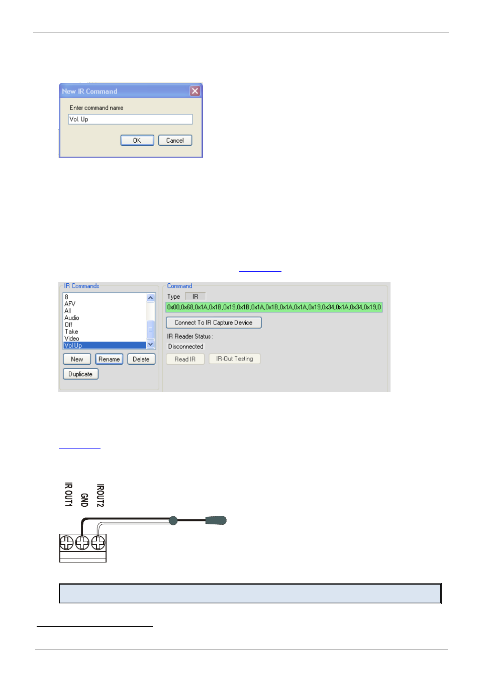
The IR command appears, as illustrated in
Figure 137: IR Command Area Window
You can test the IR command by connecting the RC unit IR terminal block connectors to the device
via the IR emitter, and then clicking the IR-Out Testing button.
shows how to connect the IR emitter
. The white striped side connects to IR OUT, the
black side connects to the Ground, and the LED Emitter Shell is affixed to the IR sensor window
with the adhesive layer.
Figure 138: IR Emitter Wiring
Note: The dual IR emitter emits a weaker IR signal that may not be detected by some devices
1
Using the Kramer 3.5mm to IR Emitter Control Cable (C-A35/IRE-10)